
Drag point recognition processing method, laser radar and computer readable storage medium

A laser radar, identification processing technology, applied in the re-radiation of electromagnetic waves, the use of re-radiation, measurement devices, etc., can solve the problems of inaccurate echo front and pulse width, measurement deviation, affecting time-of-flight measurement, etc., to improve the point The effect of cloud quality, prevention of drag points, and ease of subsequent calculation and processing

Active Publication Date: 2020-09-18
HESAI TECH CO LTD
View PDF9 Cites 11 Cited by
  • Summary
  • Abstract
  • Description
  • Claims
  • Application Information

AI Technical Summary

Problems solved by technology

In addition, the leading edge and pulse width of the echo pulse are mainly used to measure the time-of-flight and the reflectivity of the target object, so the dragging phenomenon will cause the echo leading edge and pulse width to be inaccurate, thereby affecting the measurement of the time-of-flight TOF and the reflectivity of the target object , leading to large deviations in the measurement

Method used


Image

  • Drag point recognition processing method, laser radar and computer readable storage medium
  • Drag point recognition processing method, laser radar and computer readable storage medium
  • Drag point recognition processing method, laser radar and computer readable storage medium

Examples


Embodiment Construction

[0061] The laser solution in this application will be described in detail below with reference to the accompanying drawings. In the following, only some exemplary embodiments are briefly described. As those skilled in the art would realize, the described embodiments may be modified in various different ways, all without departing from the spirit or scope of the present invention. Accordingly, the drawings and descriptions are to be regarded as illustrative in nature and not restrictive.

[0062]In describing the present invention, it is to be understood that the terms "center", "longitudinal", "transverse", "length", "width", "thickness", "upper", "lower", "front", " Back", "Left", "Right", "Vertical", "Horizontal", "Top", "Bottom", "Inner", "Outer", "Clockwise", "Counterclockwise", etc. or The positional relationship is based on the orientation or positional relationship shown in the drawings, which is only for the convenience of describing the present invention and simplif...


PUM


Abstract

The invention discloses a drag point identification processing method of a laser radar. The method comprises the following steps: acquiring waveform information of an echo corresponding to a detectionpulse; and based on the waveform information of the echo, judging whether the echo corresponds to the drag point. According to the invention, the intensity of the received echo signal is identified,if the echo amplitude is greater than the set expected value, the intensity of the next light emission is reduced, otherwise, the light emission intensity is increased. Meanwhile, a timing threshold can be determined according to the intensity of each echo signal. Through the detection and processing of the invention, the improved drag point waveform can be obtained, and more accurate measurementinformation can be obtained, such as distance information or reflectance information, etc.

Description

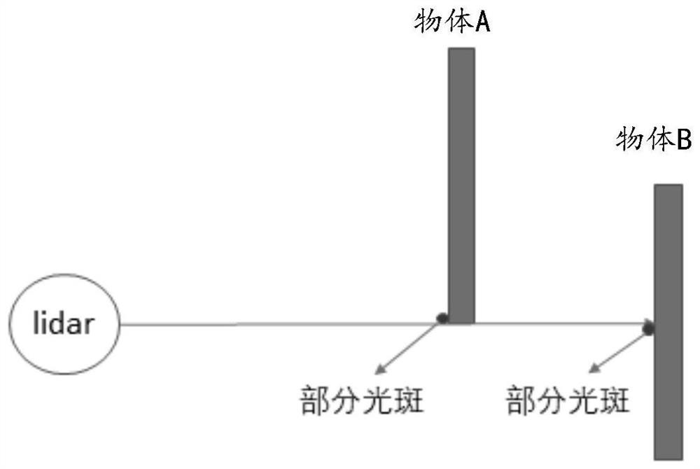
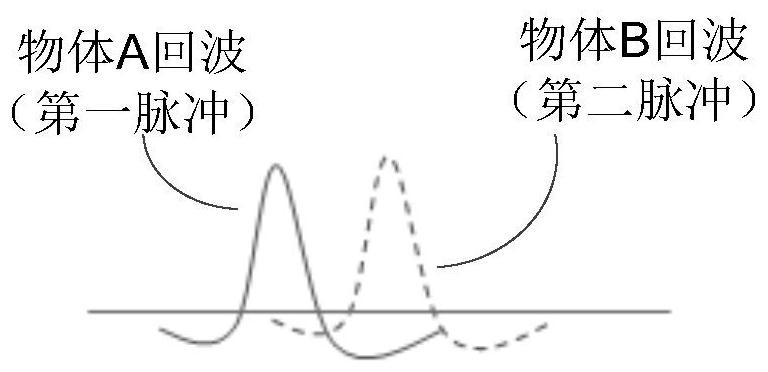
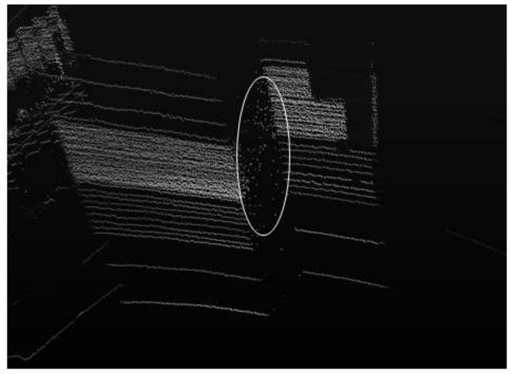
technical field [0001] The present invention relates to the technical field of laser radar, and in particular to a drag point recognition processing method of a laser radar point cloud, a laser radar capable of performing the drag point recognition processing method, and a computer-readable storage medium. Background technique [0002] Drag point refers to the phenomenon that the radar spot hits the edge of two objects that are close to each other at the same time, resulting in inaccurate leading edge and pulse width caused by the superposition of echoes, forming a general point of connection between objects. Such as Figure 1A As shown, a detection pulse sent by the lidar LiDAR is simultaneously incident on the edges of object A and object B, which are close to the front and back. It is received by the photodetector of the laser radar; part of the spot on the object B also undergoes diffuse reflection, and part of the reflected echo returns to the laser radar and is receive...

Claims


Application Information

Patent Timeline
Patent Type & Authority Applications(China)
IPC IPC(8): G01S7/48G01S7/487G01S17/02
CPCG01S7/4802G01S7/487G01S17/02
Inventor 李康平蔡瑞万曾昭明向少卿
Owner HESAI TECH CO LTD
Learn More