
Inspiratory hair cleaner for surgical debridement

A debridement and air-breathing technology, applied in the field of cleansers, can solve the problems of trouble, affecting wound healing, and hair falling into the wound easily, and achieving the effect of convenient operation.

Pending Publication Date: 2020-09-22
顾同
View PDF0 Cites 0 Cited by
  • Summary
  • Abstract
  • Description
  • Claims
  • Application Information

AI Technical Summary

Problems solved by technology

[0005] In order to overcome the disadvantages that the hair is easy to fall into the wound during the cleaning process, which affects the healing of the wound, and the hair falls on the ground, which requires people to clean up, which is troublesome and labor-intensive. The purpose of the present invention is to provide a more convenient Clean the hair to avoid the hair falling into the wound and affect the healing, and it can also collect the cleaned hair. It is easy to operate and labor-saving suction hair cleaner for surgical debridement

Method used


Image

  • Inspiratory hair cleaner for surgical debridement
  • Inspiratory hair cleaner for surgical debridement
  • Inspiratory hair cleaner for surgical debridement

Examples


Embodiment 1

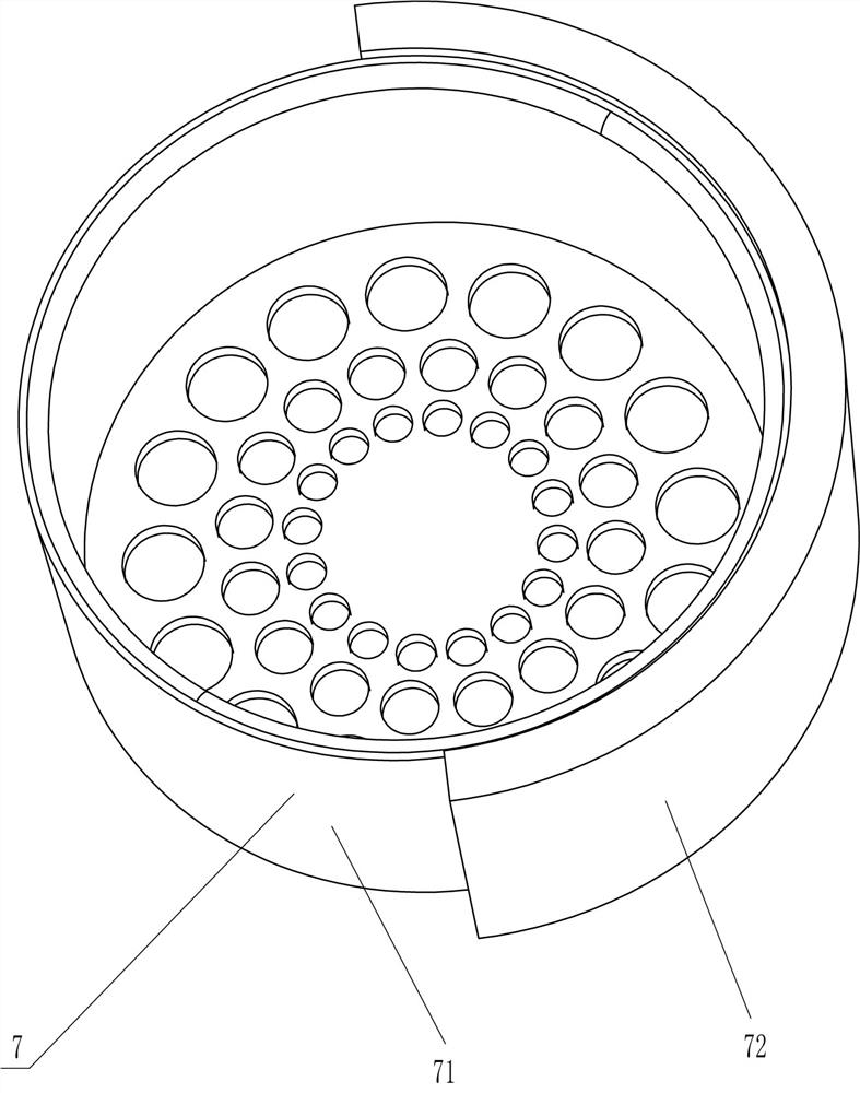
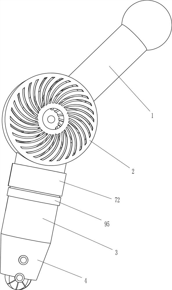
[0026] see Figure 1-Figure 6 , a suction type hair cleaner for surgical debridement, comprising a handle 1, a casing 2, an air inlet pipe 3, a tapered pipe 4, an exhaust mechanism 5, a scraping mechanism 6 and a collection mechanism 7, the outer top of the casing 2 The right side is fixed with a handle 1, and the middle of the bottom of the shell 2 is fixed with an air inlet pipe 3, which communicates with the inside of the shell 2. The air pipe 3 is internally connected, and the rear part of the shell 2 is provided with an exhaust mechanism 5, and a scraping mechanism 6 is provided between the rear part of the air inlet pipe 3 and the tapered pipe 4, and the scraping mechanism 6 is connected with the exhaust mechanism 5, and the air inlet pipe 3. The upper part is provided with a collecting mechanism 7.

[0027] The exhaust mechanism 5 includes a drive motor 51, a rotating shaft 52, a turbine blade 53, and a protective shell 54. The protective shell 54 is fixedly connected ...

Embodiment 2

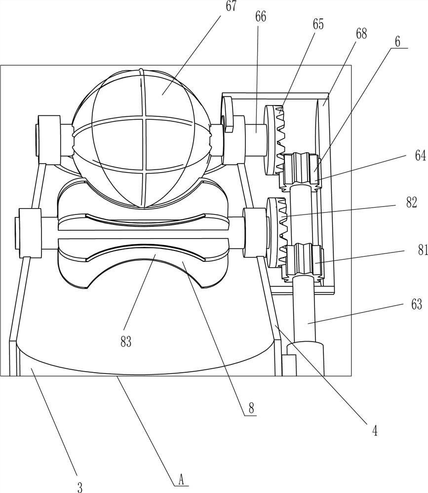
[0035] On the basis of Example 1, please refer to figure 2 with image 3 , also includes a cleaning mechanism 8, the cleaning mechanism 8 includes a third gear 81, a third bevel gear 82 and a soft plate roller 83, and a soft plate roller 83 is rotatably connected between the middle parts of the front and rear sides of the tapered tube 4. The plate roller 83 is in contact with the twill ball 67. The rear end of the soft plate roller 83 is fixedly connected with a third bevel gear 82, and the lower part of the first rotating rod 63 is fixedly connected with a third gear 81 in the circumferential direction. The third gear 81 is located in the frame body 68. It meshes with the third bevel gear 82 .

[0036] When the driving motor 51 is started, the rotation of the first rotating rod 63 also drives the rotation of the third gear 81, the rotation of the third gear 81 drives the rotation of the third bevel gear 82, the rotation of the third bevel gear 82 drives the rotation of the ...


PUM


Abstract

The invention relates to a cleaner, in particular to an inspiratory hair cleaner for surgical debridement. According to the inspiratory hair cleaner for the surgical debridement, people can clean hairmore conveniently, the situation that the hair falls into a wound to affect healing is avoided, the cleaned hair can be collected, the operation is convenient, and the labor is saved. The inspiratoryhair cleaner for the surgical debridement comprises a shell and an air inlet pipe. A handle is fixly connected to one side outside the shell; and the air inlet pipe is connected to and communicates with the side, away from the handle, of the away from the handle, of the shell. A twill ball is in touch with the periphery of a wound, a driving motor is started, so that the twill ball rotates to remove residual hair, turbine blades rotate to suck the removed hair into a screen to be collected, therefore, the operation is convenient, labor is saved, and the situation that the hair is removed andfalls into the wound to affect healing can be avoided.

Description

technical field [0001] The invention relates to a cleaner, in particular to an air suction hair cleaner for surgical debridement. Background technique [0002] Surgery is a science that studies the occurrence, development and clinical manifestations, diagnosis, prevention and treatment of surgical diseases. It is a professional department with surgical resection and repair as the main means of treatment. With the application of microsurgical technology, surgery has been greatly developed. The principle of setting up specialties of surgery in each hospital is similar to that of internal medicine, and usually corresponds to internal medicine. Surgical diseases are divided into five categories: trauma, infection, tumor, deformity and dysfunction. In surgery, there are often wounds, and the hair around the wound will remain after cleaning. The hair needs to be cleaned to avoid hair loss. into the wound and affect healing. [0003] At present, most people use tools to clean th...

Claims


Application Information

Patent Timeline
Patent Type & Authority Applications(China)
IPC IPC(8): A61B90/80
CPCA61B90/80
Inventor 顾同
Owner 顾同
Learn More