Waterproof wound cleaning device for surgery wound suture

A cleaning device and wound technology, applied in the field of cleaning devices, can solve the problems of affecting the surrounding environment, disinfectant water is easy to penetrate into the wound, etc., and achieve the effect of increasing the sealing

Inactive Publication Date: 2020-09-04
顾同
View PDF10 Cites 0 Cited by
  • Summary
  • Abstract
  • Description
  • Claims
  • Application Information

AI Technical Summary

Problems solved by technology

[0003] Existing cleaning devices, such as the Chinese patent whose patent notification number is CN209236992U discloses a general surgical wound cleaning device, including a base, a liquid storage tank, a stirring assembly, a No. 1 mixing assembly, a catheter, a No. 2 mixing assembly, and a foot pedal. Piston assembly and drain pipe; the present invention provides a wound cleaning device for general surgery, which injects medicine from the liquid inlet of the liquid storage tank, starts the motor to drive the stirring plate to stir, and realizes primary mixing; after that, the mobile device comes to the side of the patient, and the doctor While stepping on the foot pedal, the liquid medicine is drawn out from the liquid storage tank through the pedal piston assembly, and the No. 1 mixing assembly and the No. 2 mixing assembly are driven to further mix the liquid medicine, which effectively improves the uniformity of mixing, and then passes The liquid pipe leads to the nozzle to clean the wound, which is convenient and quick. The above patent has the following disadvantages: during the cleaning process, the disinfectant water easily penetrates into the wound and affects the healing, and the waste liquid that occurs during the cleaning process directly falls on the ground and affects the surrounding area. surroundings

Method used


Image

  • Waterproof wound cleaning device for surgery wound suture
  • Waterproof wound cleaning device for surgery wound suture
  • Waterproof wound cleaning device for surgery wound suture

Examples


Embodiment 1

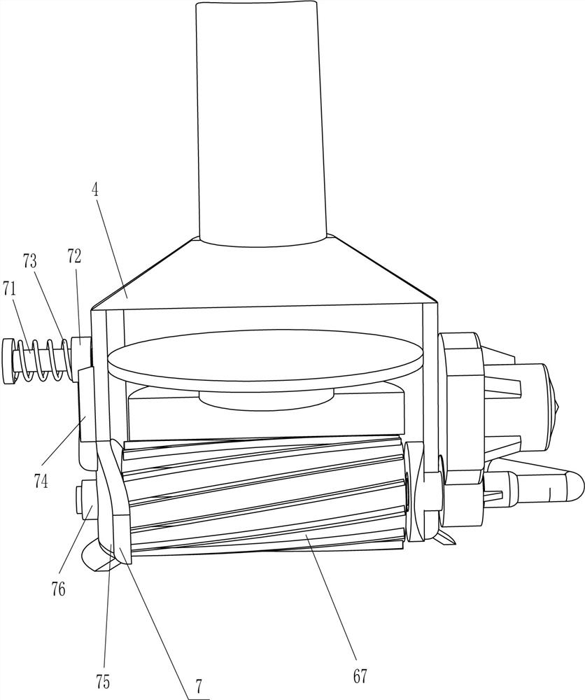
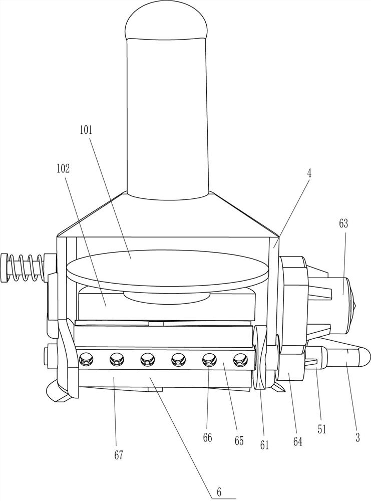
[0023] see Figure 1-Figure 4 , a kind of waterproof wound washer for suturing surgical wounds, comprising a liquid tank 1, a liquid pump 2, a liquid outlet pipe 3, a fixed cover 4, a handle 5, a hollow connecting pipe 51, a cleaning mechanism 6 and a fixing mechanism 7, the liquid tank 1 A liquid pump 2 is installed in the middle of the top, the liquid outlet end of the liquid pump 2 is connected with a liquid outlet pipe 3, the liquid outlet pipe 3 communicates with the liquid pump 2, the liquid inlet end of the liquid pump 2 is located in the liquid tank 1, and the liquid outlet pipe 3 ends The end is fixedly connected with a hollow connecting pipe 51, the hollow connecting pipe 51 communicates with the liquid outlet pipe 3, a fixed cover 4 is arranged behind the hollow connecting pipe 51, and a handle 5 is fixedly connected in the middle of the outer top of the fixed cover 4, and the handle 5 is arranged obliquely. Fixed cover 4 bottom is provided with cleaning mechanism 6...

Embodiment 2

[0030] see figure 1 Compared with Embodiment 1, the main difference of this embodiment is that in this embodiment, a waste liquid collection mechanism 8 is also included. The waste liquid collection mechanism 8 includes a collection box 81, a liquid suction pump 82 and a liquid inlet pipe 83, and the liquid tank 1, a collection box 81 is installed on the outer right side, and a liquid suction pump 82 is installed on the top of the collection box 81. The liquid outlet end of the liquid suction pump 82 is connected with a liquid inlet pipe 83. The tail end of the pipe 83 is connected in the middle of the upper right side of the fixed cover 4 , and the liquid inlet pipe 83 communicates with the fixed cover 4 .

[0031] When the medical staff moves the fixed cover 4 to make the sponge roller 67 clean around the wound, the liquid suction pump 82 can be started, and the liquid suction pump 82 operates to suck the waste liquid that occurs in the cleaning process into the liquid inlet...

Embodiment 3

[0033] see figure 1 , image 3 and Figure 5 , compared with embodiment 1 and embodiment 2, the main difference of this embodiment is that in this embodiment, an edge banding mechanism 9 is also included, and the edge banding mechanism 9 includes an arc-shaped rubber ring 91 and an arc-shaped sealing plate 92, and the matching plate The bottom of 75 is affixed with an arc-shaped sealing plate 92 , and the bottom of the fixed cover 4 is affixed with an arc-shaped rubber ring 91 , and the arc-shaped rubber ring 91 contacts and cooperates with the arc-shaped sealing plate 92 .

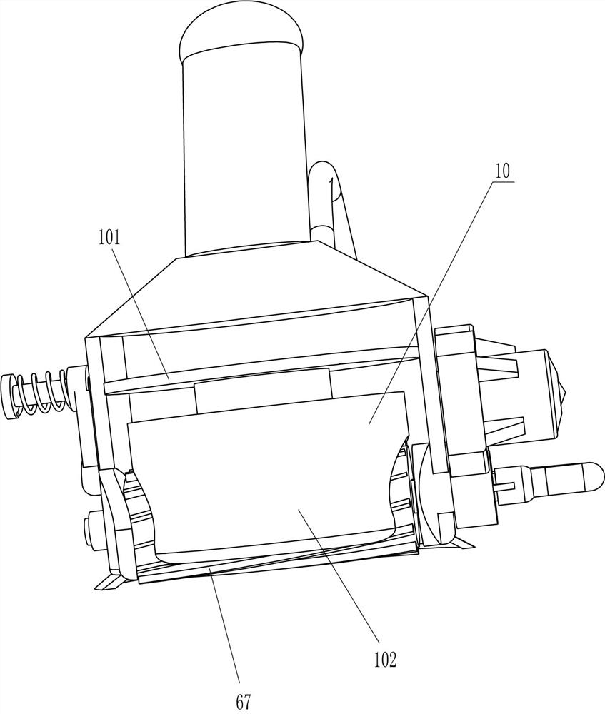
[0034] It also includes a diversion mechanism 10, the diversion mechanism 10 includes an isolation plate 101 and a filling block 102, the upper part of the inner surface of the fixed cover 4 is fixed with an isolation plate 101, and the center of the bottom of the isolation plate 101 is fixed with a filler block 102, and the filler block 102 Be positioned at sponge roller 67 tops and cooperate with it. ...


PUM


Abstract

The present invention relates to a cleaning device and particularly to a waterproof wound cleaning device for surgery wound suture. A technical problem is how to design a wound waterproof cleaning device for r surgery wound suture, which can avoid disinfectant fluid from permeating into wounds, does not influence wound healing, can also take away appearing waste liquid for collection, and does notinfluence surrounding environment. The waterproof wound cleaning device for surgery wound suture comprises a liquid box and a liquid outlet pipe; one end of the liquid box is provided with a liquid pump and the liquid pump and the liquid box are matched; and the liquid outlet pipe is connected and communicates with a liquid outlet end of the liquid pump, and a tail end is fixedly connected with ahollow connecting pipe. A fixed cover is contacted with the peripheries of the wounds, a sponge roller is also contacted with the peripheries of the wounds, the liquid pump is started to discharge the disinfectant fluid into the sponge roller, then a speed reduction motor is started, so that the sponge roller can rotate to clean the peripheries of the wounds through the disinfectant fluid, and the disinfectant fluid is prevented from being directly sprayed on the peripheries of the wounds to permeate into the wounds to affect healing.

Description

technical field [0001] The invention relates to a washer, in particular to a waterproof wound washer for suturing surgical wounds. Background technique [0002] Surgery is a science that studies the occurrence, development and clinical manifestations, diagnosis, prevention and treatment of surgical diseases. It is a professional department with surgical resection and repair as the main means of treatment. With the application of microsurgical technology, surgery has been greatly developed. The principle of setting up specialties of surgery in each hospital is similar to that of internal medicine, and usually corresponds to internal medicine. Surgical diseases are divided into five categories: trauma, infection, tumor, deformity and dysfunction. In surgery, some patients with wounds often appear for treatment. Before the wound is sutured, it is necessary to clean the wound around the wound to avoid bacteria around the wound And impurities fall into the wound and affect the ...

Claims


Application Information

Patent Timeline
Patent Type & Authority Applications(China)
IPC IPC(8): A61M35/00A61B90/80
CPCA61B90/80A61M35/20
Inventor 顾同
Owner 顾同
Why Eureka
Try Eureka