Dredger for building downspout and clearing method

A technology of unblocker and downpipe, which is applied in water supply installations, indoor sanitary plumbing installations, buildings, etc. It can solve the problems of inconvenient dredging of downpipes, achieve the effect of reducing occupied space and improving cleaning ability

Inactive Publication Date: 2020-09-22
杨小洲
View PDF9 Cites 0 Cited by
  • Summary
  • Abstract
  • Description
  • Claims
  • Application Information

AI Technical Summary

Problems solved by technology

[0006] Aiming at the deficiencies of the prior art, the present invention provides a dredger for building downpipes, which solves the problem that the existing downpipes are inconvenient to dredge

Method used


Image

  • Dredger for building downspout and clearing method
  • Dredger for building downspout and clearing method

Examples


Embodiment 1

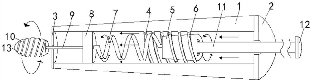
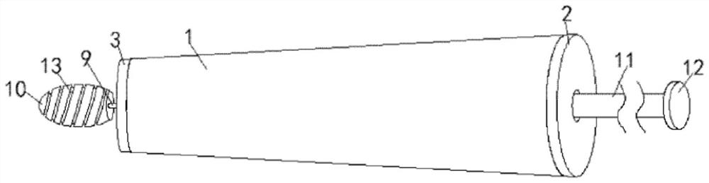
[0028] see Figure 1-2 , the present invention provides a technical solution: a dredger for building downpipes, comprising a conical sleeve 1, the top and bottom of the conical sleeve 1 are fixedly connected with a top cover 2 and a bottom cover 3, and the inner wall of the conical sleeve 1 is opened There is a spiral track 4, a plug block 5 is sleeved in the tapered sleeve 1, a spiral bar 6 is sleeved on the plug block 5, and the spiral bar 6 is sleeved in a part of the spiral track 4, the coil diameter of the spiral bar 6 and the distance between the spring wire The distance between them is equal to that of the helical track 4. For this reason, the helical bar 6 can normally mesh with the helical track 4, and only a part of the helical bar 6 is nested in the helical track 4. With the rotation of the helical bar 6, it can gradually Through the spiral track 4, the bottom of the plug block 5 is flexibly connected to the top of the receiving block 8 through the coil spring 7, th...

Embodiment 2

[0031] see Figure 1-2 , on the basis of Embodiment 1, the present invention provides a technical solution: the bottom end of the push rod 11 is fixedly connected with the top of the block 5, at this time, if you want to move the block 5 downward, you must rotate the push Rod 11, so that the coil spring 7 can be gradually compressed in a rotating manner, and at the same time, the receiving block 8 will gradually drive the dredging head 10 to descend and rotate through the transmission rod 9 in a rotating manner, when the receiving block 8 touches the bottom When the top of the cover 3, the coil spring 7 will be gradually compressed. At this time, the rotation of the dredging head 10 can be made smoother and more convenient. The corners on the platform provide enough room for the arms of the staff to use this embodiment .

Embodiment 3

[0033] see Figure 1-2 , on the basis of Embodiment 1 and Embodiment 2, the present invention provides a technical solution: the bottom end of the push rod 11 is movably connected with the top of the block 5 through a bearing, and the surface of the dredging head 10 is provided with a spiral groove 13 , at this time, just press the push block 12, the push rod 11 can be pushed down to press the plug block 5, and under the action of the spiral bar 6 and the spiral track 4, the plug block 5 can push the receiving block 8 downward through the coil spring 7 Move, at this time, the transmission rod 9 will drive the dredging head 10 to descend by rotation. When the corner space on the platform is relatively cramped and it is inconvenient for the staff to move their arms, they can directly press down. On the one hand, it is safer, and on the other hand, it can be used It is more convenient to look up, and the spiral groove 13 on the dredging head 10 can deform the garbage, and can cut...


PUM


Abstract

The invention relates to the technical field of downspout repairing tools, in particular to a dredger for a building downspout and a clearing method. The dredger for the building downspout and the clearing method aim at solving the technical problem that an existing downspout is inconvenient to dredge. In order to solve the technical problem, the dredger for the building downspout comprises a conical sleeve, the top and the bottom of the conical sleeve are fixedly connected with a top cover and a bottom cover correspondingly, and a spiral track is formed in the inner wall of the conical sleeve. A chuck is sleeved with the conical sleeve, the chuck is sleeved with a spiral strip, the spiral strip is partially sleeved with the spiral track, and the bottom of the chuck is movably connected with the top of a bearing block through a coil spring. According to the dredger, when the chuck bears pressure, the spiral strip can rotate in the spiral track, a dredging head can be made to rotate, and therefore the dredging head can gradually move downwards while rotating on its axis, and the clearing capacity to waste can be improved at this moment; and debris attached to a pipe wall is removedthrough rotating force.

Description

[0001] This application is a divisional application with the application date being August 23, 2018, and the application number being CN201810963503.7, whose invention name is a dredger for building downpipes. technical field [0002] The invention relates to the technical field of repair tools for downpipes, in particular to a dredger for downspouts in buildings and a cleaning method. Background technique [0003] The roof of the existing house is basically equipped with a roof. In rainy and snowy weather, a large amount of rainwater will be accumulated on the roof. In order to prevent rainwater from seeping into the house, leak holes will be opened at the corners of the roof and connected to the underground drainage ditch through downpipes. Or in the sewer pipe. [0004] Due to the effect of the wind, the garbage will be blown and scattered around. After a long time without rain, the falling garbage will enter the downpipe. After a long time, the downpipe will be blocked, ...

Claims


Application Information

Patent Timeline
Patent Type & Authority Applications(China)
IPC IPC(8): E03C1/302
CPCE03C1/302
Inventor 杨小洲
Owner 杨小洲
Why Eureka
Try Eureka