Lamination device and battery string preparation device

A stacking device and stacking technology, applied in the manufacture of circuits, electrical components, final products, etc., can solve the problems of low production efficiency of battery strings

Pending Publication Date: 2020-09-22
WUXI LEAD INTELLIGENT EQUIP CO LTD
View PDF0 Cites 3 Cited by
  • Summary
  • Abstract
  • Description
  • Claims
  • Application Information

AI Technical Summary

Problems solved by technology

[0004] The application provides a stacking device and a battery string preparation device to solve the problem of low efficiency of battery string preparation in the prior art

Method used


Image

  • Lamination device and battery string preparation device
  • Lamination device and battery string preparation device
  • Lamination device and battery string preparation device

Examples


Embodiment 1

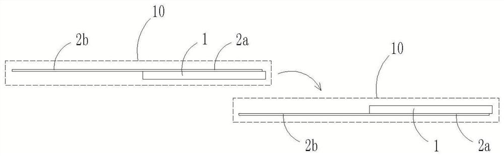
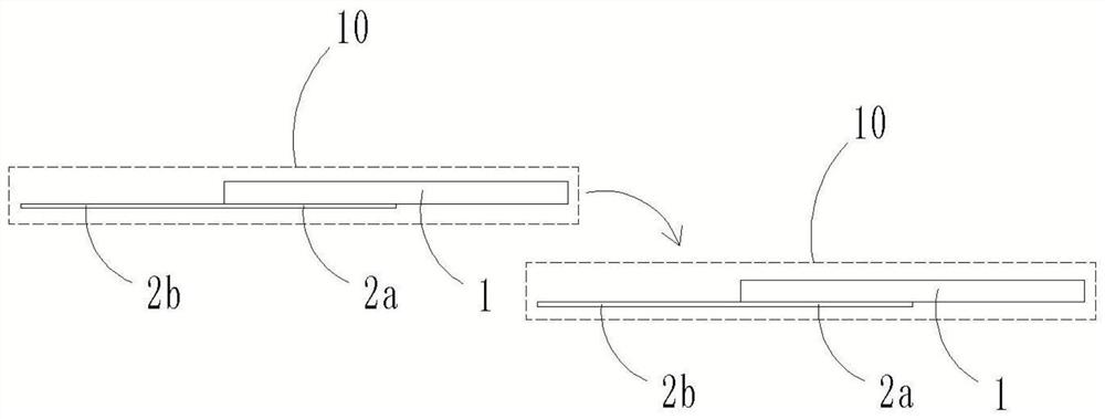
[0057] The stacking station 310 is only used for building or receiving the stringer unit 10 .

[0058] The stacking device 300 also includes a stacking driving mechanism capable of transporting the stringing unit 10 on the stacking table 310 and then stacking the stringing unit 10 .

[0059] In this embodiment, the lamination drive mechanism includes a lamination transport assembly (not shown) and a lamination transfer platform (not shown). At this time, the lamination transport assembly can transport the stringer unit 10 from the lamination table 310 and transfer the stringer unit 10 to the lamination transfer platform; the lamination transfer platform is used for the stringer unit 10 to perform lamination.

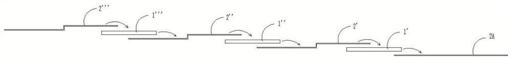
[0060] Since the second stringer unit 10 is carried by the lamination handling assembly, the stringer unit 10 transported later can be stacked on the stringer unit 10 that has been placed in place, so that the battery of the rear stringer unit 10 The sheet 1 is stacked ...

Embodiment 2

[0066] The stacking station 310 is not only used for building or receiving the stringer unit 10, but also serves as a stacking station.

[0067] At this time, the stacking device 300 includes a plurality of stacking stages 310 arranged along a straight line and capable of receiving one string welding unit 10 respectively. The stacking device 300 also includes a stacking driving mechanism; the stacking driving mechanism includes: a stacking lifting mechanism 320, connected to the stacking platform 310, and capable of driving the stacking platform 310 to move in the vertical direction; a stacking translation mechanism 330, connected to the stacking sheet stage 310, and can drive the sheet stacking stage 310 to move in a straight line.

[0068] In this embodiment, the straight line direction is the arrangement direction of the multiple stacking stages 310 .

[0069] refer to Figure 9 , Figure 16 and Figure 17 , by providing a plurality of lamination stages 310 , the lamina...

Embodiment 3

[0084] The stacking station 310 is not only used for building or receiving the stringer unit 10, but also serves as a stacking station.

[0085] At this time, the stacking device 300 includes a plurality of stacking stages 310 arranged along a straight line and capable of receiving one string welding unit 10 respectively. The stacking device 300 also includes a stacking driving mechanism; the stacking driving mechanism is used to drive a plurality of stacking stages 310 to move in a straight line. In this embodiment, the straight line direction is the arrangement direction of the multiple stacking stages 310 .

[0086] Since the surface of the battery sheet 1 is indented at the position of the grid lines to form a groove, and the solder ribbon 2 will be stuck in the groove, so, in this embodiment, the stacking table 310 approaches each other in a straight line, so that two adjacent There are two stacking stages 310, in which the second end 2b of the ribbon of one stringing un...


PUM


Abstract

The invention discloses a laminating device. The laminating device comprises a plurality of laminating tables, a laminating lifting mechanism for driving the laminating tables to move in the verticaldirection, and a laminating translation mechanism for driving the laminating tables to move in the linear direction; through movement in the vertical direction, heights of two adjacent lamination tables can be different, so the lamination tables can move in the horizontal direction, when the horizontal projections of a battery piece and a second end of a welding strip are overlapped, the battery piece is in contact with the second end of the welding strip through movement in the vertical direction, lamination is completed, and then the battery string is rapidly prepared. The invention furtherdiscloses a battery string preparation device which comprises the lamination device, a battery piece feeding device for supplying battery pieces and a solder strip feeding device for supplying solderstrips, the battery pieces and the solder strips form a series welding unit, and the lamination device can further realize lamination of the series welding units, so the battery string can be conveniently prepared.

Description

technical field [0001] The present application relates to the technical field of photovoltaic equipment, in particular to a stacking device and a battery string preparation device. Background technique [0002] When preparing battery strings by traditional methods, refer to figure 1 , usually laying a battery piece 1' first, then laying a welding ribbon 2' on the battery piece 1', and making the second end of the welding ribbon 2' fall behind the battery piece 1'; then laying a battery piece 1 ", and make the battery sheet 1" cover the second end of the laid ribbon 2', and then lay the ribbon 2" on the battery sheet 1", similarly, the second end of the ribbon 2" falls to the battery sheet 1” behind; then, lay the battery piece 1”’ on the second end of the welding strip 2”, and lay the welding strip 2”’ on the battery piece 1”’… In this way, one battery piece and one welding strip are laid successively. Finally, a battery string is formed. [0003] The fabrication method o...

Claims


Application Information

Patent Timeline
Patent Type & Authority Applications(China)
IPC IPC(8): H01L31/18
CPCH01L31/1876H01L31/188Y02P70/50
Inventor 不公告发明人
Owner WUXI LEAD INTELLIGENT EQUIP CO LTD
Why Eureka
Try Eureka