High-frequency module

A technology of high-frequency modules and metal blocks, which is applied in the fields of magnetic/electric field shielding, circuits, electric solid devices, etc., to achieve the effect of increasing the degree of freedom in design

Active Publication Date: 2020-09-22
MURATA MFG CO LTD
View PDF15 Cites 0 Cited by
  • Summary
  • Abstract
  • Description
  • Claims
  • Application Information

AI Technical Summary

Problems solved by technology

Therefore, it is difficult to form the bonding wire 103 across the component 102 without placing a large distance between the component 102 and the wire and without making it contact with the component 102

Method used


Image

  • High-frequency module
  • High-frequency module
  • High-frequency module

Examples


no. 1 approach >

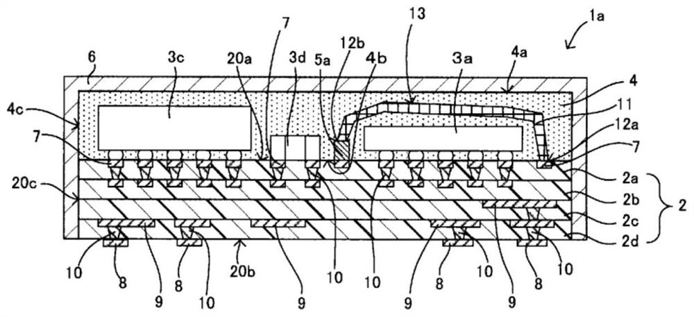
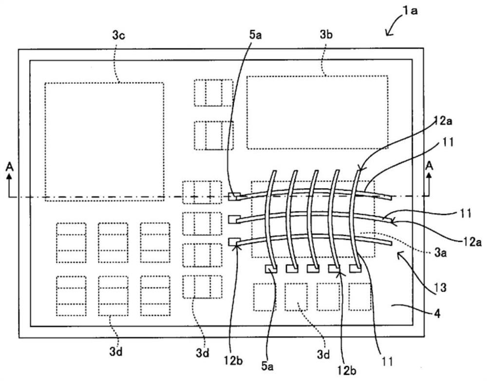
[0038] refer to Figure 1 ~ Figure 2 The high-frequency module 1a according to the first embodiment of the present invention will be described. also, figure 1 yes figure 2 The cross-sectional view in the direction of the A-A arrow, figure 2 It is a top view of the state which removed the shielding film 6 of the high frequency module 1a.

[0039] Such as figure 1 as well as figure 2 As shown, the high-frequency module 1a according to this embodiment includes a multilayer wiring board 2 (corresponding to the "wiring board" of the present invention), and a plurality of components 3a to 3d mounted on the upper surface 20a of the multilayer wiring board 2. , the sealing resin layer 4 laminated on the upper surface 20a of the multilayer wiring board 2, the shielding film 6 covering the surface of the sealing resin layer 4, the plurality of first protruding electrodes 5a mounted on the upper surface 20a of the multilayer wiring board 2, And the bonding wire 11 arranged to ...

no. 2 approach >

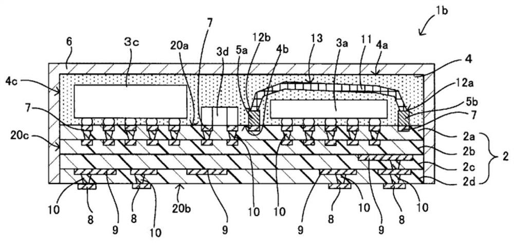
[0052] refer to Figure 3 ~ Figure 4 A high-frequency module 1b according to a second embodiment of the present invention will be described. also, image 3 is a cross-sectional view of the high-frequency module 1b, and is Figure 4 The sectional view of the BB arrow direction, Figure 4 It is a top view of the state which removed the shielding film 6 of the high frequency module 1b.

[0053] Such as Figure 3 ~ Figure 4 As shown, the high-frequency module 1b involved in this embodiment is the same as the reference Figure 1 ~ Figure 2 The high-frequency module 1 a of the first embodiment described above is different in that the second protruding electrode 5 b is arranged at the starting point 12 a (end portion on the first bonding side) of the bonding wire 11 . The other configurations are the same as those of the high-frequency module 1a of the first embodiment, so descriptions thereof will be omitted by denoting the same reference numerals.

[0054] In this embodiment,...

no. 3 approach >

[0061] refer to Figure 7 ~ Figure 8 A high-frequency module 1e according to a third embodiment of the present invention will be described. also, Figure 7 is a cross-sectional view of the high-frequency module 1e, and is Figure 8 The cross-sectional view in the direction of the arrow C-C, Figure 8 is removed Figure 7 A top view of the state after the masking film 6.

[0062] Such as Figure 7 as well as Figure 8 As shown, the high-frequency module 1e involved in this embodiment is the same as the reference Figure 1 ~ Figure 2 The high-frequency module 1a of the first embodiment described is different in that a plurality of bonding wires 11b are arranged along the periphery of the member 3a to surround the member 3a when viewed from a direction perpendicular to the upper surface 20a of the multilayer wiring board 2. at this point. The other configurations are the same as those of the high-frequency module 1a of the first embodiment, so descriptions thereof will be...


PUM


Abstract

Provided is a high-frequency module such that a projecting electrode is provided at the endpoint of the bond when forming an inter-component shield by means of a bonding wire, thereby stabilizing thelooped shape of the wire. The high-frequency module 1a is provided with a multilayered circuit board 2, a component 3a-3d installed on an upper face 20a of the multilayered circuit board 2, a shielding member 13 formed of multiple bonding wires 11 so as to cover the component 3a, and a projecting electrode 5a provided at an endpoint 12b of the bond for each of the bonding wires 11. By having the projecting electrode 5a provided at the endpoint 12b of the bond for each of the bonding wires 11, it is possible to prevent an undesirable bend in the bonding wires 11 on a second bond side and easilyform the shielding member 13 so as to cover the side face and top face of the component 3a.

Description

technical field [0001] The present invention relates to a high-frequency module provided with a shield. Background technique [0002] Various high-frequency modules are mounted on motherboards of electronic equipment such as communication terminal equipment. Among such high-frequency modules, there is a high-frequency module in which components mounted on a wiring board are sealed with a sealing resin layer. In addition, in order to block noise to components, the surface of the sealing resin layer may be covered with a shielding film. When multiple components are mounted on a wiring board, it may be necessary to block noise only for specific components, but it is difficult to shield only specific components with the shielding film covering the surface of the sealing resin layer, and the degree of freedom in design is limited. Low. Therefore, a high-frequency module capable of arranging a shield member with a high degree of design freedom has been proposed. For example, i...

Claims


Application Information

Patent Timeline
Patent Type & Authority Applications(China)
IPC IPC(8): H01L23/00H01L23/12H05K9/00
CPCH05K9/00H01L2924/19105H01L2924/19107H01L2224/48227H01L2924/181H01L23/552H01L23/5386H01L23/49811H01L23/3121H01L2924/3025H01L25/0655H01L25/16H01L24/16H01L24/13H01L2224/16227H01L2924/1421H01L2224/131H01L2924/00012H01L2924/014H01L23/142H01L2224/16225H01Q1/526H01Q23/00
Inventor 大坪喜人森本裕太
Owner MURATA MFG CO LTD
Why Eureka
Try Eureka