Automatic wire laser soldering machine

A soldering machine and wire technology, used in welding equipment, tin feeding devices, manufacturing tools, etc., can solve the problems of slow processing efficiency, small focusing spot, small heat affected zone, etc., to avoid the influence of solder quality and high soldering efficiency. , to avoid the effect of instantaneous heating

Active Publication Date: 2020-09-25
由力自动化科技(上海)有限公司
View PDF11 Cites 4 Cited by
  • Summary
  • Abstract
  • Description
  • Claims
  • Application Information

AI Technical Summary

Problems solved by technology

It is a new type of welding method, mainly aimed at the welding of thin-walled materials and precision parts, which can realize spot welding, butt welding, lap welding, sealing welding, etc., with high depth-to-width ratio, small weld width, and small heat-affected zone. The deformation is small, the welding speed is fast, the weld seam is smooth and beautiful, no treatment is required or only simple treatment is required after welding, the weld seam quality is high, no porosity, can be precisely controlled, the focusing light spot is small, the positioning accuracy is high, and it is easy to realize automation. Most of the soldering process is performed by rotating the workpiece. The solder paste is synchronized with laser spot welding for welding processing, or by adjusting the displacement of the welding head for soldering. When processing many small workpieces, manual spot welding is required, and the solder paste cannot be soldered again. During the process, it is pre-introduced into the spot welding groove, and the processing efficiency is relatively slow

Method used


Image

  • Automatic wire laser soldering machine

Examples


Embodiment 1

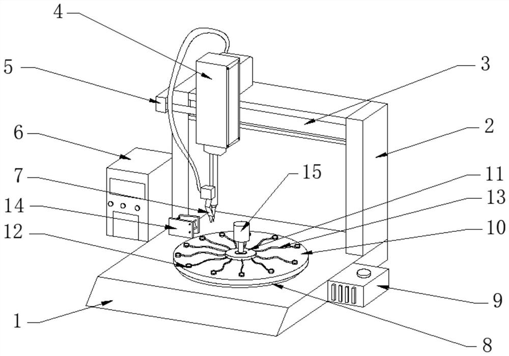
[0018] Such as figure 1 As shown, the present invention provides an automatic wire laser soldering machine, including a machine base 1, a fixed frame 2 is fixedly installed on the machine base 1, a slide rail 3 is arranged on the fixed frame 2, and a laser generator is slidably installed on the slide rail 3 4. A horizontal telescopic motor 5 is installed on the outside of the fixed frame 2, a control cabinet 6 is fixedly installed on the outside of the machine base 1, the bottom end of the laser generator 4 is connected with a laser welding head 7 through a wire, and the central surface of the machine base 1 is installed with a Turntable 8, drive motor 9 is connected to the outer side of turntable 8, workpiece disk 10 is fixedly installed on the top of turntable 8, solder paste pot 11 is installed on the central surface of workpiece disk 10, and several solder joint grooves are arranged at the edge of workpiece disk 10 12. The solder joint groove 12 and the solder paste tank 1...


PUM


Abstract

The invention discloses an automatic wire laser soldering machine. The automatic wire laser soldering machine comprises a machine base, wherein a fixed frame is fixedly arranged on the machine base; asliding rail is arranged on the fixed frame; a laser generator is arranged on the sliding rail in a sliding manner; a solder paste tank is arranged on the surface of the center of a workpiece tray; aplurality of welding spot grooves are formed in the edge of the workpiece tray and are connected to the solder paste tank through flexible pipes; a workpiece clamping plate is arranged on the outer side of the workpiece tray; a small-sized air cylinder is arranged on the top end of the solder paste tank; and a compression bar of the small-sized air cylinder is inserted in the solder paste tank. According to the automatic wire laser soldering machine, solder paste in the solder paste tank can be squeezed under the action of the compression bar at the bottom end of the small-sized air cylinder,and is transmitted to the interiors of the welding spot grooves through the flexible pipes, and the solder paste is in contact with the surfaces of workpieces, and thus, the effect of inputting the solder paste in advance can be achieved; then the workpieces are subjected to spot welding in batches by rotating a rotary table; and compared with a manual spot welding manner, the automatic wire laser soldering machine has the advantages that the soldering efficiency is relatively high, the instantaneous heating of the solder paste is avoided, and the solder paste can be placed at a room temperature firstly to prevent the soldering quality of the solder paste from being affected.

Description

technical field [0001] The invention relates to a laser soldering machine, in particular to an automatic wire laser soldering machine. Background technique [0002] Laser welding is the use of high-energy laser pulses to locally heat materials in a small area. The energy of laser radiation diffuses into the interior of the material through heat conduction, and the material is melted to form a specific molten pool. It is a new type of welding method, mainly aimed at the welding of thin-walled materials and precision parts, which can realize spot welding, butt welding, lap welding, sealing welding, etc., with high depth-to-width ratio, small weld width, and small heat-affected zone. The deformation is small, the welding speed is fast, the weld seam is smooth and beautiful, no treatment is required or only simple treatment is required after welding, the weld seam quality is high, no porosity, can be precisely controlled, the focusing light spot is small, the positioning accurac...

Claims


Application Information

Patent Timeline
Patent Type & Authority Applications(China)
IPC IPC(8): B23K1/005B23K3/06B23K3/08
CPCB23K1/0056B23K3/0607B23K3/08
Inventor 邓翔
Owner 由力自动化科技(上海)有限公司
Why Eureka
Try Eureka