Automatic welding tool clamp for steel structure reinforcing structure

A technology for automatic welding and structural strengthening, which is applied in the field of metal welding and can solve the problems of reduced labor efficiency, low welding efficiency, and difficulty in controlling the angle of inclination of flat steel.

Inactive Publication Date: 2020-09-25
张晓锋
View PDF0 Cites 3 Cited by
  • Summary
  • Abstract
  • Description
  • Claims
  • Application Information

AI Technical Summary

Problems solved by technology

[0004] 1. Since the channel steel at the lower end of the flat steel cannot be stably fixed during welding, it is easy to cause the position of the channel steel to shift during welding, thereby reducing the welding effect;
[0005] 2. When manually holding the flat steel so that the lower end of the flat steel is aligned with the upper end of the channel steel, it is difficult to control the angle of inclination of the flat steel, so that the upper end of the flat steel after welding is not on the same horizontal line, resulting in a groove on the upper end of the flat steel The steel cannot be completely welded to the upper surface of the flat steel, resulting in a waste of resources and a reduction in labor efficiency;
[0006] 3. When manually holding the flat steel and the channel steel for welding, the welding efficiency is low because each section of the flat steel needs to be re-calibrated.

Method used


Image

  • Automatic welding tool clamp for steel structure reinforcing structure
  • Automatic welding tool clamp for steel structure reinforcing structure
  • Automatic welding tool clamp for steel structure reinforcing structure

Examples


Embodiment Construction

[0030] In order to make the technical means, creative features, goals and effects achieved by the present invention easy to understand, the present invention will be further described below in conjunction with specific illustrations. It should be noted that, in the case of no conflict, the embodiments in the present application and the features in the embodiments can be combined with each other.

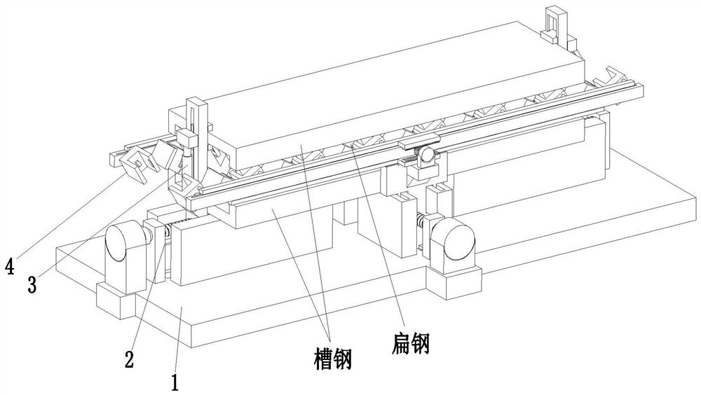
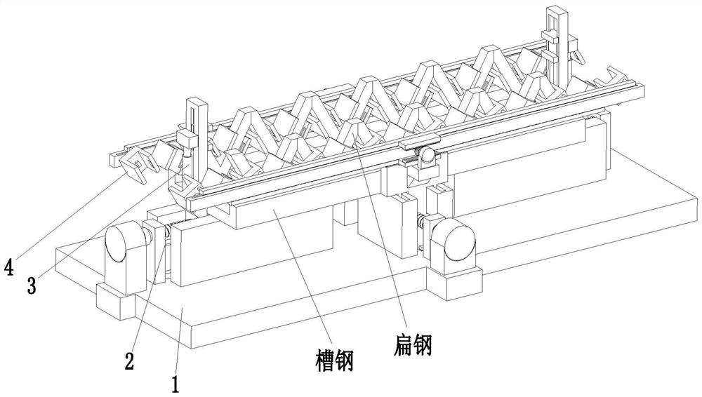
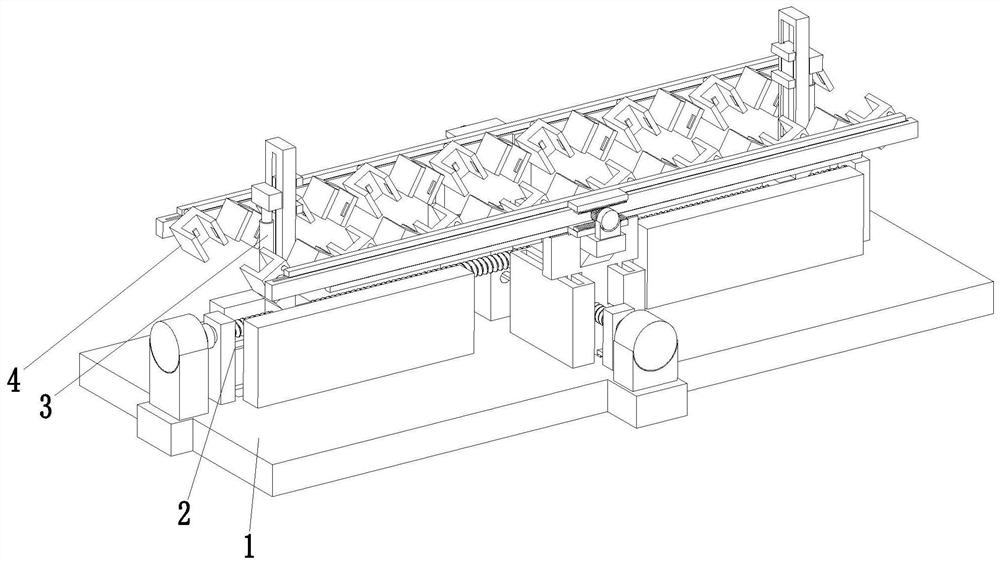
[0031] Such as Figure 1 to Figure 8 As shown, a steel structure reinforced structure automatic welding fixture includes a base 1, a clamping mechanism 2, a height adjustment mechanism 3 and a limit mechanism 4, a clamping mechanism 2 is installed on the upper end of the base 1, and the upper end of the clamping mechanism 2 Height adjustment structures are symmetrically installed on the left and right sides, and the limit mechanism 4 is symmetrically installed on the front and rear sides of the upper end of the clamping mechanism 2; the present invention can clamp and limit channel s...


PUM


Abstract

The invention relates to an automatic welding tool clamp for a steel structure reinforcing structure. The clamp comprises a base, a clamping mechanism, height adjusting mechanisms and limiting mechanisms, wherein the clamping mechanism is mounted on the upper end surface of the base, the height adjusting mechanisms are symmetrically mounted on the left and right sides of the upper end of the clamping mechanism, and the limiting mechanisms are symmetrically mounted on the front and back sides of the upper end of the clamping mechanism. The clamp can solve the problems when the steel structure reinforcing structure is welded that the welding effect is reduced as a result of deviation of a channel steel slot during welding as channel steel at the lower end of flat steel cannot be stably fixedduring welding; the channel steel on the upper end surface of the flat steel cannot be welded to the upper end surface of the flat steel completely as the upper end surfaces of the welded flat steelare not in a same horizontal line because it is hard to control the inclining angle of the flat steel when the flat steel is held manually to align the lower end of the flat steel with the upper end surface of the channel steel; and the welding efficiency is low as it is needed to calibrate the angle when one section of the flat steel is welded every time and the like.

Description

technical field [0001] The invention relates to the field of metal welding, in particular to an automatic welding fixture for a reinforced structure of a steel structure. Background technique [0002] Steel structure is a structure composed of steel materials, which is one of the main building structure types. The structure is mainly composed of beam steel, steel column, steel truss and other components made of section steel and steel plate; Welding seam, bolt or rivet connection, because of its light weight and easy construction, is widely used in large factories, venues, super high-rise and other fields; when erecting steel structure buildings, it is usually necessary to weld flat steel and section steel to form a Steel structure reinforced structure; [0003] In the prior art, when welding the reinforced structure of the steel structure, the lower end of a section of flat steel is usually welded to the upper end surface of the channel steel in sequence, and there is a ce...

Claims


Application Information

Patent Timeline
Patent Type & Authority Applications(China)
IPC IPC(8): B23K37/04
CPCB23K37/0443
Inventor 张晓锋王传福
Owner 张晓锋
Why Eureka
Try Eureka