
Metal plate clamping device for following to clamp

A clamping device and metal plate technology, applied in the direction of workpiece clamping devices, manufacturing tools, etc., can solve the problems of insufficient clamping distance, inconvenience, resource waste efficiency, etc., to avoid insufficient clamping force and expand application Scope, effect of convenient scope of application

Inactive Publication Date: 2020-09-25
杭州悟伦机械科技有限公司
View PDF0 Cites 3 Cited by
  • Summary
  • Abstract
  • Description
  • Claims
  • Application Information

AI Technical Summary

Problems solved by technology

[0003] At present, the metal plate clamping device at this stage will cause the clamping distance to be too far during processing if the metal plate is too long, resulting in insufficient clamping force, vibration of the metal plate, etc., resulting in a decline in processing quality or even failure, resulting in waste of resources and low efficiency, and It is very inconvenient to change the clamping thickness as the thickness of the metal plate changes.

Method used


Image

  • Metal plate clamping device for following to clamp
  • Metal plate clamping device for following to clamp
  • Metal plate clamping device for following to clamp

Examples


Embodiment Construction

[0017] All the features disclosed in this specification, or all disclosed methods or steps in the process, except for mutually exclusive features and / or steps, can be combined in any manner.

[0018] Combine below Figure 1-5 The present invention will be described in detail. For the convenience of description, the orientations mentioned below are now specified as follows: figure 1 The vertical, horizontal, front and rear directions of the projection relationship are the same.

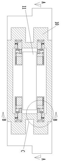
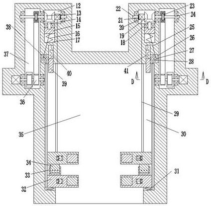
[0019] A metal plate clamping device that follows the clamping and fixing of the device of the present invention includes a box body 10, the front end of the box body 10 is provided with a metal plate groove 35 that opens forward, and the back end wall of the metal plate groove 35 is provided There is an outlet slot 11 that opens backwards. The left and right end faces of the metal plate slot 35 are provided with slide rail grooves 30 that open to the metal plate groove 35. The slide rail groove 30 is fixed...


PUM


Abstract

The invention discloses a metal plate clamping device for following to clamp. The metal plate clamping device comprises a box body; a metal plate slot with a forward opening is arranged in the front end surface of the box body; an outlet slot with a backward opening is arranged in the rear end wall of the metal plate slot; slide rail slots with openings towards the metal plate slot are arranged inthe left and right end surfaces of the metal plate slot; guide rails are fixedly arranged on the end surfaces, far away from the metal plate slot, of the slide rail slots; the guide rails are in sliding connection with clamping slide blocks symmetrically arranged in front and back; the front end surface of the front clamping slide block is connected with the slide rail slots through a spring; a clamping block sliding chute with an opening towards the outlet slot is arranged at the end, located at the metal plate slot, of each clamping slide block; clamping blocks are in sliding connection with the clamping block sliding chutes; a folding telescopic air bag is fixedly connected between the end surface of each clamping block far away from the outlet slot and each clamping block sliding chute; the folding telescopic air bags are fixedly connected with air pipes. Two ends of a processing section can be clamped following a processing position when an excessively long metal sheet is processed, and therefore insufficient clamping force caused by too long distance is avoided.

Description

Technical field [0001] The invention relates to the technical field related to metal plate processing, in particular to a metal plate clamping device that follows clamping and fixing. Background technique [0002] Metal is a substance with luster (that is, strong reflection of visible light), rich ductility, easy to conduct electricity, and heat conduction. The vast majority of metal elements on the earth exist in nature in a chemical state. The metal plate is a plate made of metal materials. [0003] At this stage of the metal plate clamping device, if the metal plate is too long, it will cause the clamping distance to be too long during processing, which will result in insufficient clamping force, vibration of the metal plate, etc., which will lead to a decline in processing quality or even failure, resulting in waste of resources and low efficiency, and The clamping thickness cannot be changed with the thickness of the metal plate, which is very inconvenient. Summary of the i...

Claims


Application Information

Patent Timeline
Patent Type & Authority Applications(China)
IPC IPC(8): B25B11/00
CPCB25B11/00
Inventor 赵悦
Owner 杭州悟伦机械科技有限公司
Learn More