
Compaction device of large circular sawing machine

A technology of a circular sawing machine and a pressing device, which is applied in the directions of positioning device, clamping, and supporting, can solve the problem of easy to produce violent vibration, reduce the feed and cutting speed of the saw blade, the life of the saw blade and the surface quality of the sawing surface. Equipment damage and other problems, to achieve the effect of large cylinder pressure, uniform pressure distribution, and good results

Inactive Publication Date: 2020-06-23
东莞市固达机械制造有限公司
View PDF7 Cites 4 Cited by
  • Summary
  • Abstract
  • Description
  • Claims
  • Application Information

AI Technical Summary

Problems solved by technology

Through actual use, it is found that this pressing method is prone to vibration of the material plate during processing, especially when sawing thin material plates, due to the lack of rigidity of the material plate itself, the uncompressed side is more likely to produce severe vibrations. It will cause great damage to the life of the saw blade, the surface quality of the sawing surface and the equipment itself, so the feed and cutting speed of the saw blade have to be reduced, which greatly reduces the working efficiency of the equipment

Method used


Image

  • Compaction device of large circular sawing machine
  • Compaction device of large circular sawing machine
  • Compaction device of large circular sawing machine

Examples


Embodiment Construction

[0020] The following will clearly and completely describe the technical solutions in the embodiments of the present invention with reference to the accompanying drawings in the embodiments of the present invention. Obviously, the described embodiments are only some, not all, embodiments of the present invention.

[0021] In describing the present invention, it should be understood that the terms "center", "longitudinal", "transverse", "length", "width", "thickness", "upper", "lower", "front", " Orientation indicated by rear, left, right, vertical, horizontal, top, bottom, inside, outside, clockwise, counterclockwise, etc. The positional relationship is based on the orientation or positional relationship shown in the drawings, and is only for the convenience of describing the present invention and simplifying the description, rather than indicating or implying that the referred device or element must have a specific orientation, be constructed and operated in a specific orientat...


PUM


Abstract

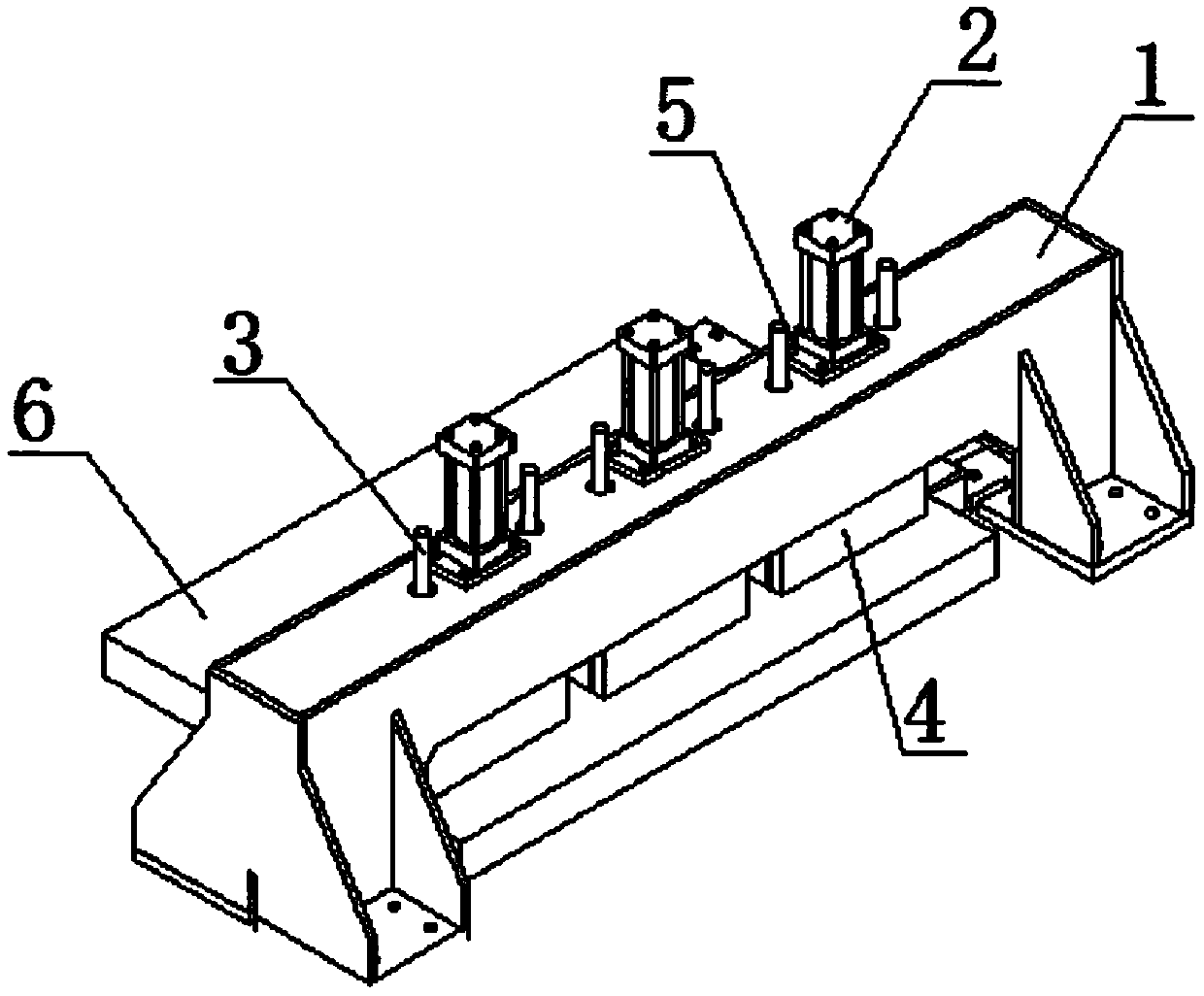
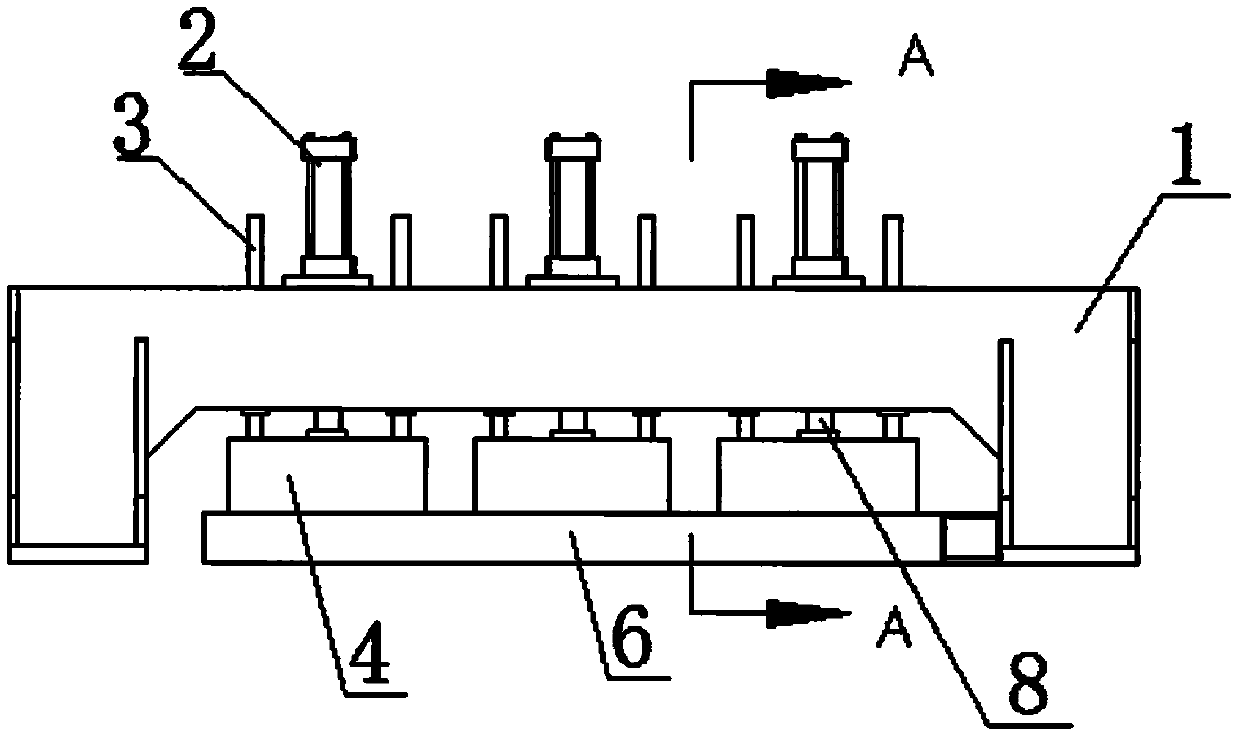
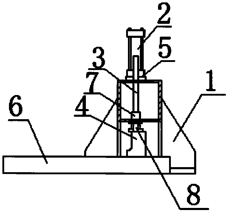
The invention relates to the field of circular sawing machines, in particular to a compaction device of a large circular sawing machine. The compaction device comprises a steel part portal frame. Three pressing oil cylinders are horizontally mounted and fixed to the top end of the steel part portal frame, the output end of each steel part portal frame is connected to an oil pressure telescopic rod, the bottom end of the oil pressure telescopic rod is connected and fixed to a pressing plate, the bottom end of the pressing plate is arranged on the material plate, and guide bars are vertically mounted and fixed to two sides of the top end surface of each pressing plate, the guide bars are slidably inserted into guide sleeves, and the guide sleeves are mounted and fixed to the steel part portal frame. By clamping the material plates in the sawing machine by way of compacting the material plate by means of an oil pressure of the portal frame, the pressures of the oil cylinders are acted tothe material plates by means of actions of pressure heads. By means of characteristics of large pressures of the oil cylinders and stable and adjustable oil cylinders, the material plates can be clamped firmly. It is ensured that the material plates are stable and do not vibrate during sawing. The three oil cylinders are arranged in a ''-'' shape, so that the pressures acted to the material platesare uniformly distributed. The large circular sawing machine has a good effect of sawing large-sized material plates of different sizes particularly.

Description

technical field [0001] The invention relates to the technical field of circular sawing machines, in particular to a pressing device for a large circular sawing machine. Background technique [0002] The GD1510 circular sawing plate is pressed using a gantry structure, and the material plate is pressed by a downward pressure cylinder. In the past, when the sawing machine used the downward pressure method to compress the material plate, it was generally pressed on one side, that is, the downward force only acts on one side of the saw edge of the material plate, while the other side is in a free state. Through actual use, it is found that this pressing method is prone to vibration of the material plate during processing, especially when sawing thin material plates, due to the lack of rigidity of the material plate itself, the uncompressed side is more likely to produce severe vibrations. It will cause great damage to the life of the saw blade, the surface quality of the sawing...

Claims


Application Information

Patent Timeline
IPC IPC(8): B23Q3/08
CPCB23Q3/082
Inventor 凌益民黄朋飞
Owner 东莞市固达机械制造有限公司
Learn More