Electric vehicle charging system

An electric vehicle and power supply technology, which is applied in the direction of electric vehicle charging technology, electric vehicles, charging stations, etc., can solve the problems that have not been solved, the popularity of charging piles is not enough, and vehicle charging, etc., to achieve the effect of improving the flexibility of power supply

Pending Publication Date: 2020-09-25
深圳市瑞能时代科技有限公司
View PDF0 Cites 0 Cited by
  • Summary
  • Abstract
  • Description
  • Claims
  • Application Information

AI Technical Summary

Problems solved by technology

However, since the location of the charging pile is relatively fixed, and the current popularity of the charging pile is not enough, if the car travels to the designated location before the power is exhausted, but the vehicle cannot be charged due to damage to the charging pile or other reasons, and the car at this time When the remaining power of the battery is not enough to support the vehicle to the next charging station, the driver can only charge the vehicle by calling a tow truck to tow the vehicle to the next charging station, and then restore the normal operation of the vehicle. driving function
The above-mentioned situation is a problem that is easy to occur in the daily driving process of existing electric vehicles, but this problem has not been solved

Method used


Image

  • Electric vehicle charging system
  • Electric vehicle charging system
  • Electric vehicle charging system

Examples


Embodiment Construction

[0024] Below, the present invention will be further described in conjunction with the accompanying drawings and specific implementation methods. It should be noted that, under the premise of not conflicting, the various embodiments described below or the technical features can be combined arbitrarily to form new embodiments. .

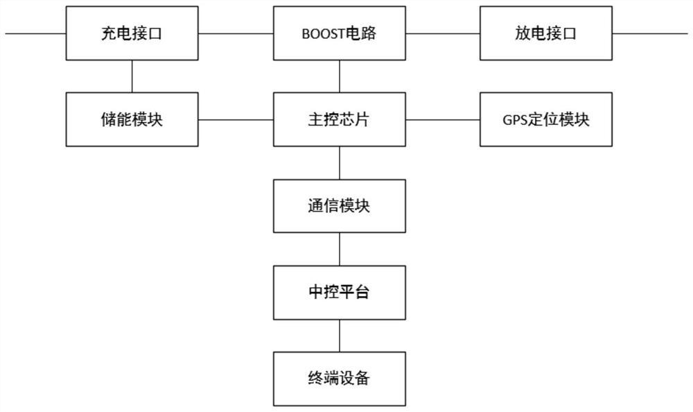
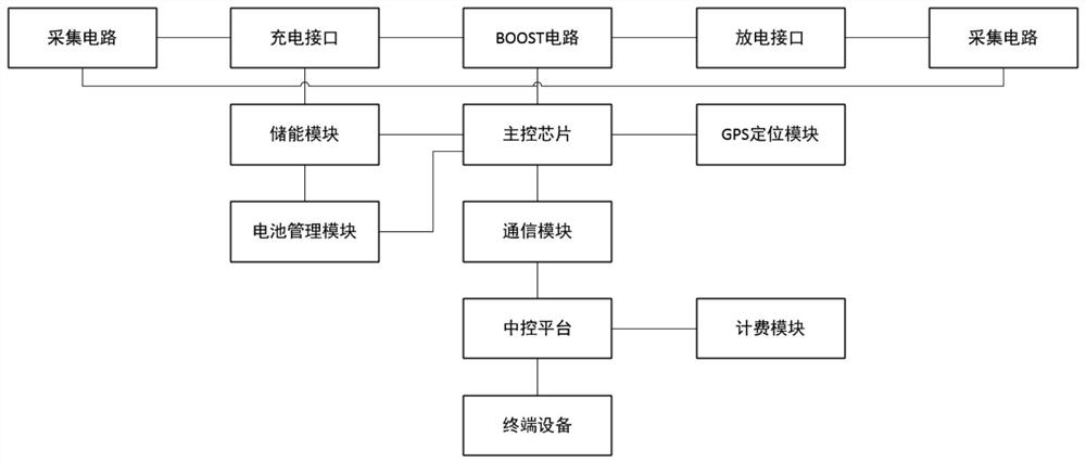
[0025] This embodiment provides an electric vehicle charging system, which is used together with a portable charging device to improve the flexibility of electric vehicle charging.

[0026] In the cooperation mode of transportation companies, a portable charging device can be configured in each electric vehicle, and each electric vehicle is equipped with at least one portable charging device, and the portable charging device is presented in the form of a box, so users can put The portable charging device is placed in the trunk, that is, it does not take up too much space inside the electric vehicle, and it can also be taken out when the electric vehicl...


PUM


Abstract

The invention discloses an electric vehicle charging system which comprises a portable charging device which is configured in each electric vehicle, a central control platform and terminal equipment.Each portable charging device comprises a box body and a charging wire. An integrated circuit board is arranged in the box body and comprises a BOOST circuit, an energy storage module, a main controlchip, a GPS positioning module and a communication module, the input terminal and the output terminal of the BOOST circuit are correspondingly connected with a charging interface and a discharging interface, and the two interfaces are detachably connected with charging wires respectively; the charging interface is connected with the energy storage module, the energy storage module is connected with the main control chip, and the main control chip is connected with the GPS positioning module and the communication module. The central control platform is in signal communication with the communication module in each portable charging device and is bound with the portable charging device; and terminal equipment is configured in each electric vehicle, is bound with each portable charging device,and is in signal communication with the central control platform. Opposite charging of any two electric vehicles can be achieved, and the flexibility is improved.

Description

technical field [0001] The invention relates to the technical field of charging and discharging of new energy electric vehicles, in particular to an electric vehicle power supply system. Background technique [0002] At present, the development of electric vehicles is an important way to improve the competitiveness of the automobile industry, ensure energy security and develop a low-carbon economy. However, existing electric vehicles all require the driver to drive the car to a charging pile at a fixed location, and the battery of the electric vehicle can only be charged after the charging pile is connected. However, since the location of the charging pile is relatively fixed, and the current popularity of the charging pile is not enough, if the car travels to the designated location before the power is exhausted, but the vehicle cannot be charged due to damage to the charging pile or other reasons, and the car at this time When the remaining power of the battery is not eno...

Claims


Application Information

Patent Timeline
Patent Type & Authority Applications(China)
IPC IPC(8): B60L53/68B60L53/66B60L53/62B60L53/30
CPCB60L53/30B60L53/62B60L53/66B60L53/68Y02T10/70Y02T10/7072Y02T90/12Y02T90/16
Inventor 毛广甫
Owner 深圳市瑞能时代科技有限公司
Why Eureka
Try Eureka