Isolation structure for continuous beam grouting layer and grouting method

A technology of isolation structure and isolation layer, which is applied in the direction of bridges, bridge construction, erection/assembly of bridges, etc., and can solve problems such as difficulty in realization, easy residue of formwork, easy penetration into beam holes, etc.

Pending Publication Date: 2020-09-25
CHINA MCC5 GROUP CORP
View PDF0 Cites 0 Cited by
  • Summary
  • Abstract
  • Description
  • Claims
  • Application Information

AI Technical Summary

Problems solved by technology

This traditional construction method has the following shortcomings: 1. Due to the high requirements on the precision and flatness of the contact surface of the two beams, the traditional method is difficult to achieve
2. Foam glue or formwork is easy to remain in the joints of track beams, which is difficult to remove and difficult to operate
3. Foam glue has strong fluidity, is difficult to control, and is easy to penetrate into the beam hole, causing blockage in the hole and hindering subsequent stretching

Method used


Image

  • Isolation structure for continuous beam grouting layer and grouting method

Examples


Embodiment 1

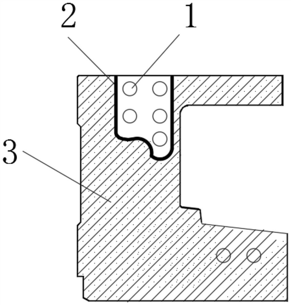
[0018] Such as figure 1 As shown, in this embodiment, an isolation structure for continuous beam grouting layer includes two adjacent simply supported beams 3 and a flexible isolation layer 2 arranged between the two simply supported beams 3. The flexible isolation layer 3 surrounds the outer side of the prestressed beam hole 1.

[0019] Surround the flexible isolation layer 3 on the outside of the prestressed piercing hole 1, so that the flexible isolation layer 3 is in sealed contact with the simply supported beams 2 on both sides, so as to form an isolation area isolated from the grouting area, and grouting is performed in the grouting area No, it can prevent concrete from entering the isolation area. The flexible deformation of the flexible isolation layer 3 can fill up the gap between the flexible isolation layer 3 and the simply supported beam 2, enhance the sealing strength of the flexible isolation layer 3 and the simply supported beam 2, and prevent concrete from leakin...

Embodiment 2

[0022] On the basis of the foregoing embodiment, in this embodiment, a supporting structure for supporting the flexible isolation layer 2 is provided between the two simply supported beams 3. The use of a supporting structure to support the flexible isolation layer 2 is beneficial to keep the position of the flexible isolation layer 2 stable and avoid displacement of the flexible isolation layer 2 under the impact of concrete.

[0023] In this embodiment, the supporting structure uses steel bars. A number of short steel bars are prefabricated or embedded around the prestressed beam hole 1, and the short steel bars are used to support and limit the flexible isolation layer 2.

[0024] The short steel bars can be arranged on the inner and outer sides of the flexible isolation layer 2. When concrete is poured or the isolation area is filled later, the short steel bars do not need to be removed and no additional impurities are introduced.

Embodiment 3

[0026] On the basis of the foregoing embodiment, in this embodiment, the flexible isolation layer 2 adopts a flexible hose. In this way, the volume of the flexible hose can be controlled by water injection or air injection, so that the flexible isolation layer 2 can be placed between two adjacent simply supported beams 3. After the flexible hose contacts the simply supported beam 3, the elastic Water or air is continuously injected within the deformation limit to make the flexible hose and the simply supported beam 3 fully contact to eliminate the gap, thereby increasing the sealing strength between the flexible hose and the simply supported beam 3.

[0027] In this embodiment, one end of the flexible hose is closed, and the other end is provided with an opening. By providing an opening helps to reduce the risk of leakage.

[0028] The opening of the flexible hose is provided with a locking structure. In this way, during construction, the opening is locked by the locking structur...


PUM


Abstract

The invention discloses an isolation structure for a continuous beam grouting layer and a grouting method. A flexible isolation layer is arranged between every two adjacent simply supported beams, theflexible isolation layers go surround the outer sides of prestress penetrating holes, the flexible isolation layer is connected with the simply supported beams on the two sides in a sealed mode, andconcrete is poured into the area between the simply supported beams and the area on the outer sides of the flexible isolation layer. The isolation structure has the following beneficial effects: the flexible isolation layer is arranged between the two simply supported beams and thus a required shape can be formed by bending according to requirements; the area where the prestress strand penetratingholes are located is isolated from a grouting area; some tiny gaps can be filled by utilizing the elastic deformation of the flexible isolation layer so as to ensure the sealing strength of the flexible isolation layer and the simply supported beam; concrete is prevented from entering the area where the prestressed tendon penetrating hole is located; the flexible isolation layer can avoid the prestressed penetrating hole after being bent, the influence of construction on the prestressed penetrating hole is avoided, and the flexible isolation layer can be conveniently taken out after construction is completed, so that subsequent construction is prevented from being influenced.

Description

Technical field [0001] The invention relates to the technical field of bridge construction, in particular to an isolation structure and a grouting method for continuous beam grouting layer. Background technique [0002] At present, most of the simple-supported beams and variable-continuous beams in our country are constructed by the post-tensioning method. When the two simply-supported beams are pouring concrete at the pouring belt position after the contact opening, the pre-stressed beam holes must be reserved first. Usually thick formwork or expanded foam glue is used to cover the pre-stressed piercing hole area to separate the post-cast concrete from the pre-stressed piercing hole and prevent the concrete from entering the piercing hole area. This traditional construction method has the following shortcomings: 1. Due to the high requirements for the accuracy and flatness of the contact surface of the two beams, the traditional method is difficult to achieve. 2. Foam glue or t...

Claims


Application Information

Patent Timeline
IPC IPC(8): E01D21/00
CPCE01D21/00
Inventor 罗利袁弘毅游洋陈磊
Owner CHINA MCC5 GROUP CORP
Why Eureka
Try Eureka