A method and device for casing strain monitoring based on axially arranged optical fibers

A technology of strain monitoring and optical fiber strain, which is applied in the direction of measuring devices, using optical devices, and measuring the change force of optical properties of materials when they are stressed, can solve the problems of complex engineering construction technology, engineering construction pressure and cost pressure. , It is difficult to grasp the largest area situation and other problems, to achieve the effect of convenient and accurate monitoring

Active Publication Date: 2021-12-10
中船重工(大连)海防环保科技有限公司
View PDF9 Cites 0 Cited by
  • Summary
  • Abstract
  • Description
  • Claims
  • Application Information

AI Technical Summary

Problems solved by technology

However, the disadvantage of this method is that if it is necessary to accurately monitor the casing deformation in the full well depth range, a large number of cross-sectional lateral sensors need to be arranged, which will cause engineering construction pressure and cost pressure will be unimaginable
[0004] In summary, there are the following disadvantages in the existing casing damage monitoring technology: 1. The corresponding engineering construction process is complicated; 2. It can only monitor the situation of fortified sections. In practical applications, only key sections can be set and fortified sections The probability of being in the extreme area of ​​strain is low, and it is difficult to grasp the maximum area

Method used


Image

  • A method and device for casing strain monitoring based on axially arranged optical fibers
  • A method and device for casing strain monitoring based on axially arranged optical fibers
  • A method and device for casing strain monitoring based on axially arranged optical fibers

Examples


Embodiment Construction

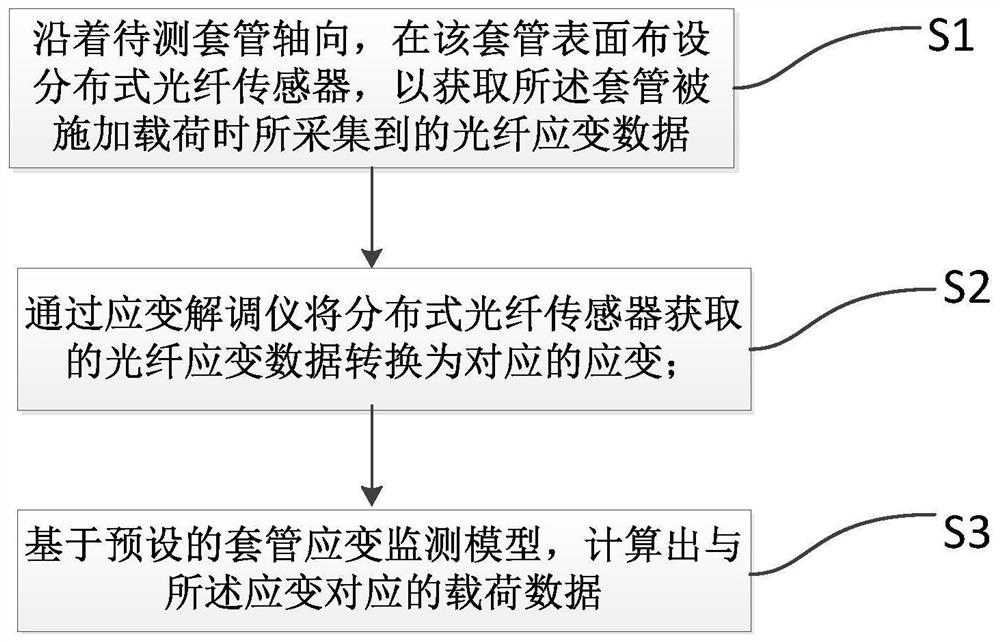
[0043] In order to make the object, technical solution and advantages of the present invention clearer, the present invention will be further described in detail below in conjunction with the accompanying drawings and embodiments. It should be understood that the specific embodiments described here are only used to explain the present invention, not to limit the present invention.

[0044] Unless otherwise defined, all technical and scientific terms used herein have the same meaning as commonly understood by one of ordinary skill in the technical field of the invention. The terms used herein in the description of the present invention are for the purpose of describing specific embodiments only, and are not intended to limit the present invention. It can be understood that the terms "first", "second" and the like used in the present invention can be used to describe various elements herein, but these elements are not limited by these terms. These terms are only used to disting...


PUM


Abstract

The embodiment of the present invention discloses a bushing strain monitoring method and system based on axially arranging optical fibers, which includes: S1, along the axial direction of the bushing to be measured, laying distributed optical fiber sensors on the surface of the bushing to obtain all The optical fiber strain data collected when the casing is loaded; S2, converting the optical fiber strain data obtained by the distributed optical fiber sensor into strain; S3, based on the preset casing strain monitoring model, calculating the corresponding load data. The present invention detects real-time optical fiber strain through a distributed optical fiber sensor; at the same time, records the applied axial tensile load value and radial bending load value, and obtains the load data corresponding to the output value of the distributed optical fiber sensor based on the casing strain monitoring model , the casing strain monitoring model can express the corresponding relationship between the sensor output value and the casing load (axial and radial). The invention can conveniently and accurately monitor the deformation and load of the casing.

Description

technical field [0001] The invention relates to the technical field of casing deformation monitoring, in particular to a method and device for casing strain monitoring based on axially arranged optical fibers. Background technique [0002] In the field of oil exploitation, it often happens that oil well casings are damaged in pieces. Typically, mining conditions are adjusted according to the damage to avoid magnification of the problem. For damaged cased wells, they can only be repaired, and those that cannot be repaired can only be scrapped, and the annual loss is huge. [0003] In recent years, a number of research teams have made beneficial attempts to monitor casing damage using optical fiber strain sensing technology, conducted laboratory and field tests, obtained effective monitoring data, and published relevant academic papers; the usual practice is: use FRP strengthened fiber optic cables are arranged axially for tension and compression sensing, and multiple fiber ...

Claims


Application Information

Patent Timeline
Patent Type & Authority Patents(China)
IPC IPC(8): G01B11/16G01L1/24
CPCG01B11/18G01L1/241G01L1/243
Inventor 毛翎王晋张艳廖小满刘增武徐翔
Owner 中船重工(大连)海防环保科技有限公司
Why Eureka
Try Eureka