A method for arranging sensors for valve hall monitoring of a converter valve

A technology for monitoring sensors and layout methods, which is applied in measuring devices, radiation pyrometry, instruments, etc., and can solve problems such as threshold value reduction, easy pollution accumulation, and abnormal conduction of converter valves.

Active Publication Date: 2020-07-07
GUANGZHOU BUREAU CSG EHV POWER TRANSMISSION +1
View PDF4 Cites 0 Cited by
  • Summary
  • Abstract
  • Description
  • Claims
  • Application Information

AI Technical Summary

Problems solved by technology

[0003] In the prior art, the thyristor electronic circuit (TE board) and the thyristor voltage detection board (TVM board) boards are directly exposed to the environment of the valve hall, without shell protection, easy to accumulate dirt, leading to misconduction of the boards and causing accidents. For example, in the process of switching from the standby state to the blocking state of the DC transmission system, there will be many abnormal conduction events of the converter valve. Under operating conditions, the threshold value of its backup trigger function is greatly reduced, resulting in abnormal conduction of the converter valve during the normal charging process of the converter.
At present, there is a lack of a set of solutions for comprehensive monitoring of the valve hall of the converter valve in practical applications

Method used


Image

  • A method for arranging sensors for valve hall monitoring of a converter valve
  • A method for arranging sensors for valve hall monitoring of a converter valve
  • A method for arranging sensors for valve hall monitoring of a converter valve

Examples


Embodiment

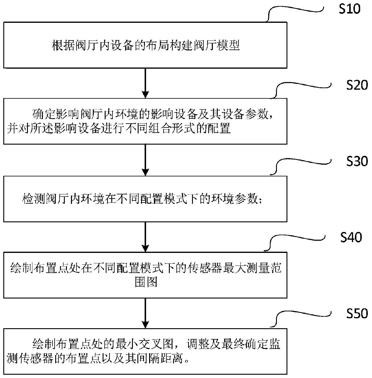
[0026] see Figure 1 to Figure 6 , a valve hall monitoring sensor arrangement method for a converter valve, comprising the following steps:

[0027] Step S10: Build a valve hall model according to the layout of operating equipment and auxiliary equipment in the valve hall; the auxiliary equipment includes one or any combination of air conditioners, fresh air equipment, and water cooling equipment.

[0028] Analyze the layout of operating equipment and auxiliary equipment in the valve hall of the converter valve, measure the position of the equipment in the valve hall, use AUTOCAD to draw the layout of the valve hall, and accurately mark the equipment in the valve hall in the layout of the valve hall The location and distance dimensions are used to provide the valve hall model for the selection of measurement points and the drawing of the distribution map of the valve hall environmental measurement parameters.

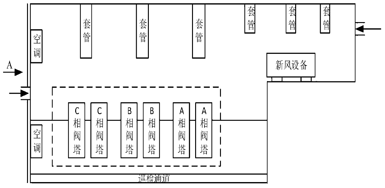
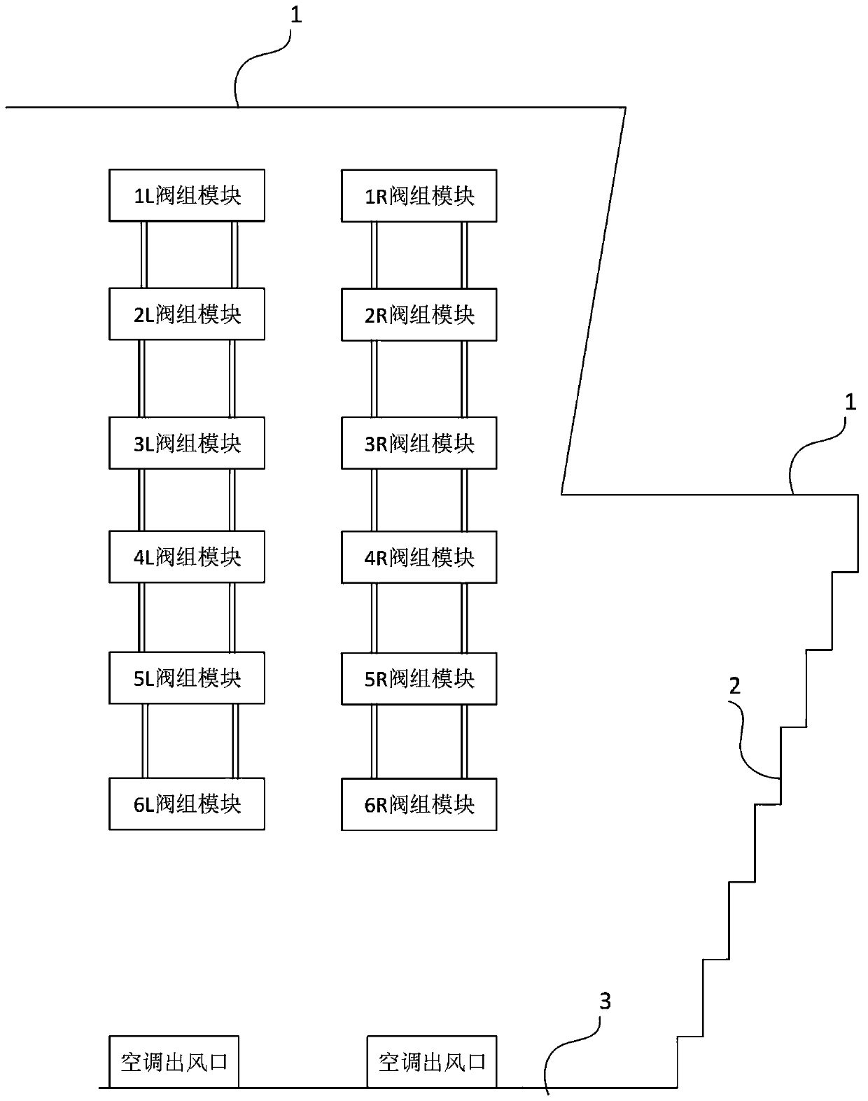
[0029] Taking the valve hall of ±500kV converter station as an ex...


PUM


Abstract

The invention discloses a converter valve hall monitoring sensor arrangement method, which relates to the technical field of direct current power transmission. The converter valve hall monitoring sensor arrangement method comprises the following steps: constructing a valve hall model according to the layout of equipment in the valve hall; determining affecting equipment affecting the environment in the valve hall and parameters thereof, and performing configuration of different combination forms on the affecting equipment; preliminarily selecting arrangement points of fixed monitoring sensorsbased on the valve hall model and detecting the environmental parameters of the environment in the valve hall under different combination forms; using a mobile monitoring sensor to determine the maximum measurement ranges of the fixed monitoring sensors, and drawing a map of the maximum measurement ranges of the sensors at the arrangement points in different combination forms; and drawing a minimum cross map at the arrangement points according to the map of the maximum measurement ranges of the sensors, and adjusting and finally determining the arrangement points of the monitoring sensors andthe spacing distance.

Description

technical field [0001] The invention relates to the technical field of direct current transmission, in particular to a method for arranging sensors for valve hall monitoring of a converter valve. Background technique [0002] DC transmission technology has developed rapidly in my country in recent years, and its advantages in long-distance power transmission, cross-regional networking, and flexible dispatching are becoming increasingly apparent. The converter valve is an important core electrical equipment in the converter station. Its function is to realize rectification and inversion. Strictly speaking, from the perspective of operating experience, the cleanliness of the entire valve hall has a huge impact on the converter valve and its auxiliary control units. [0003] In the prior art, the thyristor electronic circuit (TE board) and the thyristor voltage detection board (TVM board) boards are directly exposed to the environment of the valve hall, without shell protectio...

Claims


Application Information

Patent Timeline
Patent Type & Authority Patents(China)
IPC IPC(8): G06F30/18G01J5/00G01N33/00G01N15/06G01N21/00
CPCG01J5/00G01N15/06G01N21/00G01N33/0075
Inventor 陶敏梁家豪梁秉岗周翔胜江一何平张朝辉梁律马远
Owner GUANGZHOU BUREAU CSG EHV POWER TRANSMISSION
Why Eureka
Try Eureka