Mouth mirror with suction tube structure

A technology of suction tube and mouth mirror, which is applied in oral mirror, endoscope, medical science, etc., to achieve the effect of conveniently attracting saliva, conveniently collecting cooling water, and conveniently using

Inactive Publication Date: 2020-09-29
魏运秀
View PDF6 Cites 1 Cited by
  • Summary
  • Abstract
  • Description
  • Claims
  • Application Information

AI Technical Summary

Problems solved by technology

At present, the mouth mirrors on the market have the basic functions of lighting and pulling. In the clinical operation process, there

Method used


Image

  • Mouth mirror with suction tube structure
  • Mouth mirror with suction tube structure
  • Mouth mirror with suction tube structure

Examples


Embodiment Construction

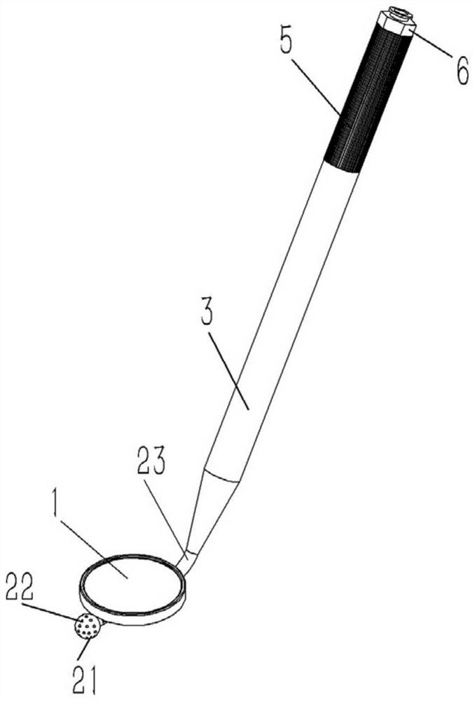
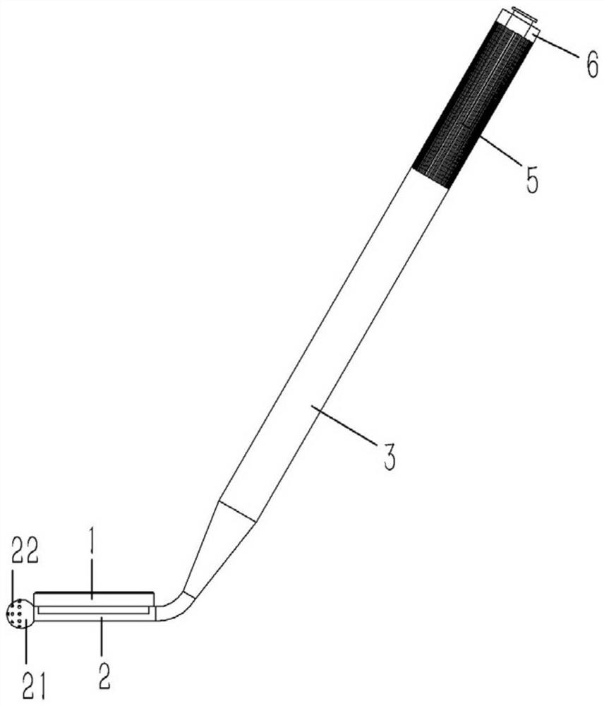
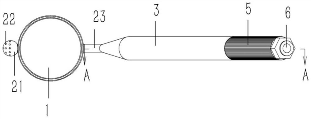
[0018] Example: see Figures 1 to 4 As shown, a mouth mirror with a suction tube structure includes a mirror body 1 of the mouth mirror. A catheter 2 is welded and fixed on the back of the mirror body 1. One end of the catheter 2 protrudes from the mirror body 1 and is formed with a spherical suction head 21 to attract A plurality of suction holes 22 are formed on the head 21; the other end of the conduit 2 protrudes from the mirror body 1 and is bent to form an inclined connecting pipe 23, which is plugged and fixedly connected to the handle 3 of the mouth mirror.

[0019] The rear end surface of the handle 3 is formed with a threaded hole 31, the rear end of the connecting pipe 23 is inserted into the threaded hole 31 of the handle 3, and the threaded hole 31 of the handle 3 is screwed with an extension tube 4, and the extension tube 4 is inserted into the sleeve On the connecting pipe 23 , the rear end of the extension pipe 4 protrudes from the handle 3 and is fixed with a ...


PUM


Abstract

The invention discloses a mouth mirror with a suction tube structure. The mouth mirror comprises a mirror body of the mouth mirror, wherein a guide tube is welded and fixed to the back surface of themirror body; one end of the guide tube extends out of the mirror body to form a spherical suction head; a plurality of suction holes are formed in the suction head; the other end of the guide tube extends out of the mirror body to be bent to form an inclined connecting tube; and a handle of the mouth mirror is fixedly connected to the connecting tube in an inserting manner. According to the mouthmirror disclosed by the invention, the suction guide tube is used as a support of the mouth mirror, and the suction head which is of a spherical structure is designed on the head portion of the suction guide tube, so that saliva is conveniently sucked, and cooling water is conveniently collected; and meanwhile, the length of the adopted suction guide tube portion can also be adjusted, so that themouth mirror is convenient to use.

Description

technical field [0001] The invention relates to the technical field of surgical instruments, in particular to a mouth mirror with a suction tube structure. Background technique [0002] At present, the mouth mirror is the most commonly used small surgical instrument in oral clinical practice. Its main purposes are to obtain indirect vision, traction, indirect lighting and perspective; obtaining indirect vision refers to observing the tooth surface that cannot be directly seen with a dental mirror, or the inside of the mouth. structure; pulling refers to the use of the mouth mirror to pull the patient's cheeks, mucous membranes, or tongue internally so that the doctor can see the surface of the tooth covered by these soft tissues; indirect lighting is simply the use of the mouth mirror to reflect light onto the tooth surface in the dark areas of the mouth ; Transillumination refers to the technique of using a mouth mirror to reflect light through the front teeth. At present,...

Claims


Application Information

Patent Timeline
IPC IPC(8): A61B1/247A61B1/015A61C17/06
CPCA61B1/247A61B1/015A61C17/06A61C17/084A61C17/088
Inventor 魏运秀
Owner 魏运秀
Why Eureka
Try Eureka