Oil tank capable of realizing scrap-removing and cleaning

A fuel tank cleaning technology, which is applied in the field of hydraulic system fuel tanks, can solve problems such as doping, and achieve the effect of avoiding oil ingress and maintaining oil cleanliness

Inactive Publication Date: 2020-09-29
SHANDONG HUALIAN MINING
View PDF4 Cites 0 Cited by
  • Summary
  • Abstract
  • Description
  • Claims
  • Application Information

AI Technical Summary

Problems solved by technology

However, in fact, after the oil used in the hydraulic system has been used for a period of time, due to various factors such as friction and corrosion, the oil is doped with iron filings and other impurities. It must be stopped and cleaned regularly before the hydraulic system can resume normal work.

Method used


Image

  • Oil tank capable of realizing scrap-removing and cleaning
  • Oil tank capable of realizing scrap-removing and cleaning
  • Oil tank capable of realizing scrap-removing and cleaning

Examples


Embodiment 1

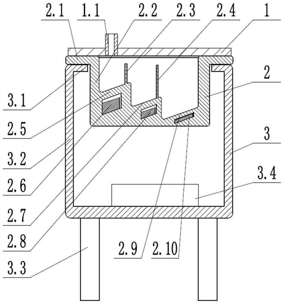
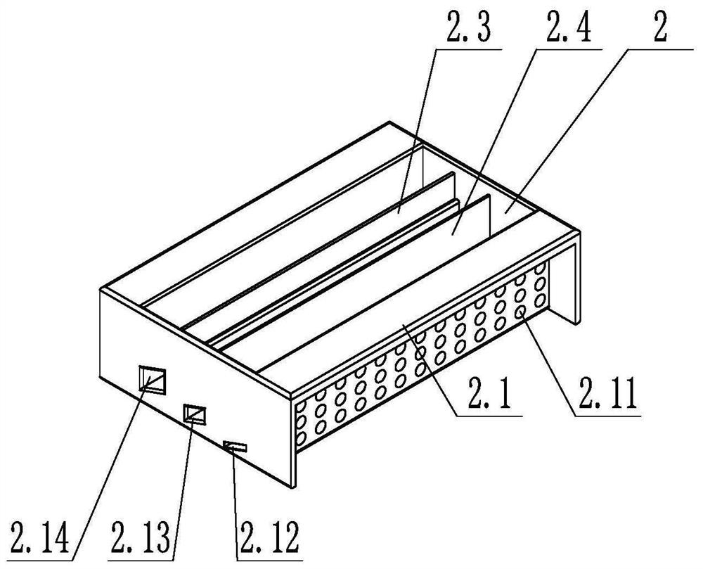
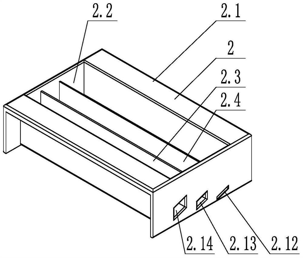
[0031] like Figure 1 to Figure 4 As shown, the cleaning oil tank for removing debris according to the present invention includes an inner oil tank 2 and an outer oil tank 3, the inner oil tank 2 is set on the upper part of the outer oil tank 3, and the upper part of the inner oil tank 2 is provided with an end cover 1.

[0032] in:

[0033] The inner oil tank 2 includes an inner oil tank body 2.2, and an outer frame plate 2.1 is provided on both sides of the top of the inner oil tank body 2.2, and a filter step is provided on the inner bottom of the inner oil tank body 2.2, and a filter step is provided on the inner oil tank body 2.2 on the other side of the filter step. Oil hole 2.11; a storage tank is provided below the filter step, a magnet is arranged in the storage tank, and the storage tank is not connected with the inner cavity of the inner oil tank; a filter screen can be provided on the filter step. Both ends of the accommodating tank are provided with plugs. Filte...

Embodiment 2

[0038] like figure 1 As shown, the filter steps include a first filter step 2.5, a second filter step 2.7 and a third filter step 2.9, the first filter step has an upward inclination angle of 20° relative to the horizontal line, and the second filter step has an upward inclination angle of 20° relative to the horizontal line. The third filter step has an upward inclination angle of 35° relative to the horizontal line. All the other are with embodiment 1.

Embodiment 3

[0040] like figure 1 As shown, the filter steps include a first filter step 2.5, a second filter step 2.7 and a third filter step 2.9, the first filter step has an upward inclination angle of 15° relative to the horizontal line, and the second filter step has an upward inclination angle of 25° relative to the horizontal line. The third filter step has an upward inclination angle of 30° relative to the horizontal line. All the other are with embodiment 1.


PUM


Abstract

The invention relates to an oil tank capable of realizing scrap-removing and cleaning, belonging to the technical field of oil tanks of hydraulic systems. The oil tank comprises an inner oil tank andan outer oil tank, wherein the upper portion of the outer oil tank is sleeved with the inner oil tank; an end cap is arranged on the upper portion of the inner oil tank; the inner oil tank comprises an inner oil tank body, outer frame plates are outwards arranged on the two sides of the top of the inner oil tank body, a filtering step is upwards obliquely arranged at the inner bottom of the inneroil tank body, and an oil passing hole is formed in the part, located on the other side of the filtering step, of the inner oil tank body; a containing groove is formed below the filtering step, a magnet is arranged in the containing groove, and the containing groove does not communicate with the inner cavity of the inner oil tank; an inlet pipe is arranged on the end cover and penetrates throughthe end cover to communicate with the inner cavity of the inner oil tank; the outer oil tank comprises an outer oil tank body; and the outer oil tank body comprises a supporting plate with two top sides arranged inwards, and one side of the outer oil tank body communicates with an outlet pipe. The cleaning agent can be used for cleaning oil and keeping the cleanliness of the oil.

Description

technical field [0001] The invention relates to a cleaning oil tank for chip removal, which belongs to the technical field of hydraulic system oil tanks. Background technique [0002] The oil used in the hydraulic system must maintain the cleanliness of the oil to ensure the normal operation of the hydraulic system. However, in fact, after the oil used in the hydraulic system has been used for a period of time, due to various factors such as friction and corrosion, the oil is doped with iron filings and other impurities, and the hydraulic system must be shut down for regular cleaning before the hydraulic system can resume normal work. Contents of the invention [0003] The technical problem to be solved by the present invention is: to overcome the deficiencies of the prior art and provide a cleaning oil tank capable of cleaning the oil and maintaining the cleanliness of the oil. [0004] The cleaning oil tank for dedusting according to the present invention includes an in...

Claims


Application Information

Patent Timeline
Patent Type & Authority Applications(China)
IPC IPC(8): B01D36/00
CPCB01D36/00
Inventor 张广超刘太亮齐俊杰
Owner SHANDONG HUALIAN MINING
Why Eureka
Try Eureka