A rotary stainless steel soup ladle stamping equipment
A stamping equipment, stainless steel technology, applied in the field of rotary stainless steel spoon stamping equipment, can solve the problems of easy hand injury by the machine, troublesome operation, low work efficiency, etc., to achieve high work efficiency, convenient operation, and avoid injury Effect
- Summary
- Abstract
- Description
- Claims
- Application Information
AI Technical Summary
Problems solved by technology
Method used
Image
Examples
Embodiment 1
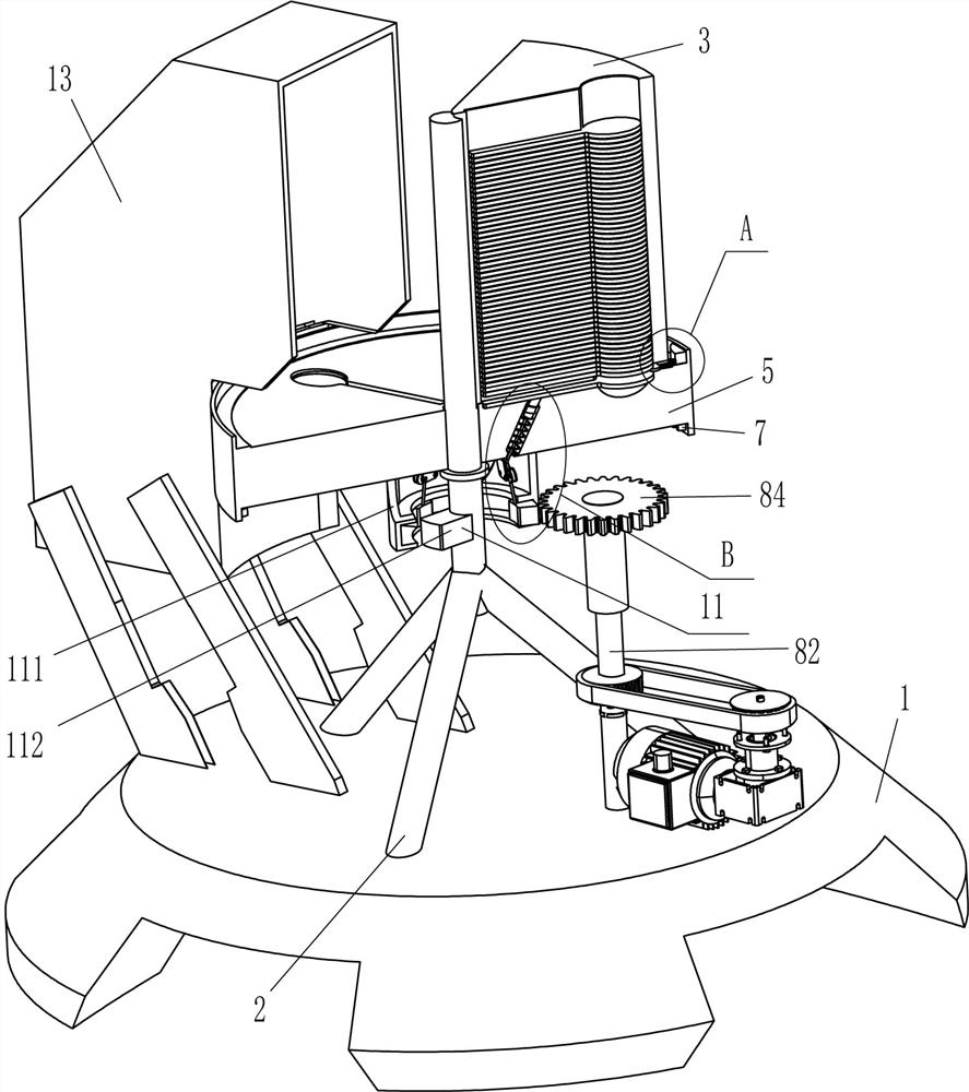
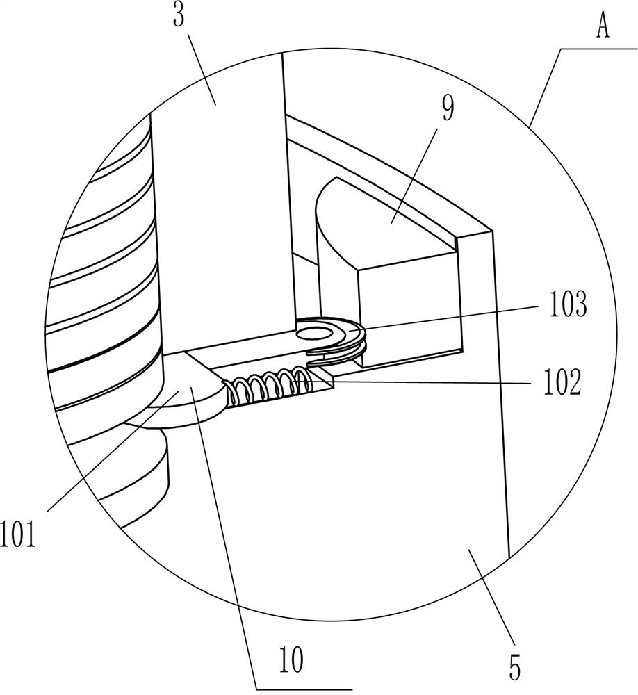
[0023] A rotary stainless steel spoon stamping equipment, such as Figure 1-Figure 3 As shown, it includes a base 1, a support rod 2, a blanking frame 3, a punching machine 4, a circular block 5, an inner gear 7, a driving mechanism 8, a convex block 9 and a separation mechanism 10. The top of the base 1 is fixed with a The support rod 2, the upper right rear part of the support rod 2 is installed with a blanking frame 3, the right lower rear side of the blanking frame 3 is provided with a separation mechanism 10, and the lower part of the support rod 2 is connected with a circular block 5 in a circumferential rotation. The inner side of the circular block 5 is in contact with the bottom of the blanking frame 3. There are three placement slots 6 evenly spaced at the top of the circular block 5. The placement slots 6 are matched with the blanking frame 3, and the inner upper part of the circular block 5 is evenly spaced circumferentially. There are three convex blocks 9 fixed o...
Embodiment 2
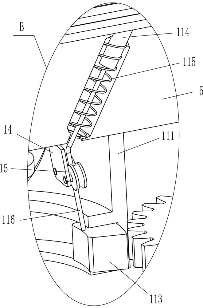
[0030] On the basis of Example 1, as figure 2 and Figure 4 As shown, it also includes a pushing mechanism 11. The pushing mechanism 11 includes a ring block 111, a strong magnet 112, an iron block 113, a push rod 114, a second spring 115 and a pull wire 116. The bottom of the circular block 5 is fixed at the center of the circle. There is a ring block 111, the support rod 2 is located in the ring block 111, the inner side of the ring block 111 is slidably provided with three iron blocks 113 at the lower part, the front side of the lower part of the support rod 2 is fixedly connected with a strong magnet 112, the strong magnet 112 and the iron block 113 In cooperation, a push rod 114 is slidably provided on the inner side of the bottom of the placement slot 6. A second spring 115 is connected between the bottom end of the push rod 114 and the inside of the circular block 5, and a pull wire 116 is also connected to the bottom end of the push rod 114, and the tail of the pull w...
Embodiment 3
[0033] On the basis of Example 1 and Example 2, as figure 1 , figure 2 and Figure 4 As shown, it also includes a support plate 12 and a stop frame 13. Two support plates 12 are fixed symmetrically front and rear on the left side of the top of the base 1, and a stop frame 13 is installed between the upper parts of the inner sides of the four support plates 12. The stop frame 13 and Round block 5 fits.
[0034] It also includes a mounting plate 14 and a wire wheel 15. Three mounting plates 14 are fixedly connected to the inner bottom of the circular block 5 at uniform intervals in the circumferential direction. The mounting plates 14 correspond to the pull wires 116. A wire pulley 15 is connected in the form, and each pull wire 116 passes through the corresponding two wire pulleys 15 to cooperate with it.
[0035] First, the operator places the collection container under the blocking frame 13. When the push rod 114 pushes out the stainless steel spoon in the placing slot 6,...
PUM
 Abstract
Description
Claims
Application Information
 - R&D
- Intellectual Property
- Life Sciences
- Materials
- Tech Scout
- Unparalleled Data Quality
- Higher Quality Content
- 60% Fewer Hallucinations
Browse by: Latest US Patents, China's latest patents, Technical Efficacy Thesaurus, Application Domain, Technology Topic, Popular Technical Reports.
© 2025 PatSnap. All rights reserved.Legal|Privacy policy|Modern Slavery Act Transparency Statement|Sitemap|About US| Contact US: help@patsnap.com


