Machining arm

A mechanical processing and arm technology, applied in the direction of manipulator, control mechanical energy, claw arm, etc., can solve the problem that the length of the manipulator cannot be adjusted automatically, and achieve the effect of simple structure, small size, and precise and controllable length change.

Inactive Publication Date: 2020-09-29
张洁
View PDF1 Cites 0 Cited by
  • Summary
  • Abstract
  • Description
  • Claims
  • Application Information

AI Technical Summary

Problems solved by technology

[0004] The technical problem to be solved by the present invention is to provide a mechanical processing arm to solve the problem that the length of the mechanical arm cannot be automatically adjusted in the prior art

Method used


Image

  • Machining arm
  • Machining arm
  • Machining arm

Examples


Embodiment 1

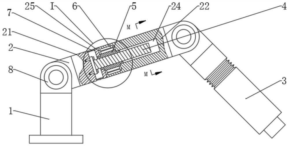
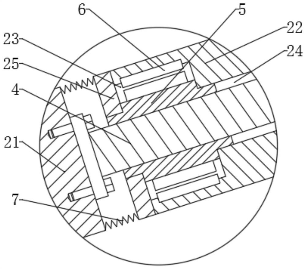
[0023] Depend on Figure 1 ~ Figure 3 As shown, a mechanical processing arm includes a base 1, a first arm 2 and a second arm 3, the base 1, the first arm 2 and the second arm 3 are hinged in sequence, and the base 1, the second arm The hinge shafts of the first arm 2 and the second arm 3 are connected with a rotary motor 8, the first arm 2 and the second arm 3 have the same structure, and the first arm 2 includes a first connecting seat 21 and a second connecting seat 21. Seat 22, the threaded rod 4 is fixedly connected to the first connecting seat 21, the second connecting seat 22 is provided with a rotor chamber 23 and a screw chamber 24, the rotor chamber 23 is provided with a rotor tube 5 capable of rotating around its own axis, and the rotor tube 5 is a magnetic material, the rotor tube 5 is provided with a magnetic steel 53, the rotor tube 5 is sleeved on the threaded rod 4, and the rotor cavity 23 is also provided with a stator winding 6 for driving the rotor tube 5 to...

Embodiment 2

[0033] Depend on Figure 1 ~ Figure 3 As shown, a mechanical processing arm includes a base 1, a first arm 2 and a second arm 3, the base 1, the first arm 2 and the second arm 3 are sequentially hinged, and the base 1, the second arm The hinge shafts of the first arm 2 and the second arm 3 are connected with a rotary motor 8, the first arm 2 and the second arm 3 have the same structure, and the first arm 2 includes a first connecting seat 21 and a second connecting seat 21. Seat 22, the threaded rod 4 is fixedly connected to the first connecting seat 21, the second connecting seat 22 is provided with a rotor chamber 23 and a screw chamber 24, the rotor chamber 23 is provided with a rotor tube 5 capable of rotating around its own axis, and the rotor tube 5 is a magnetic material, the rotor tube 5 is provided with a magnetic steel 53, the rotor tube 5 is sleeved on the threaded rod 4, and the rotor cavity 23 is also provided with a stator winding 6 for driving the rotor tube 5 t...


PUM


Abstract

The invention discloses a machining arm, relates to the field of mechanical arms, and solves the problem that the length of a mechanical arm cannot be automatically adjusted in the prior art. The machining arm is characterized in that the machining arm comprises a base, a first support arm and a second support arm, wherein the base, the first support arm and the second support arm are hinged in sequence; the first support arm and the second support arm are of the same structure; the first support arm comprises a first connecting seat and a second connecting seat; a threaded rod is fixedly connected to the first connecting seat; a rotor cavity and a screw cavity are arranged in the second connecting seat; a rotor tube is arranged in the rotor cavity, the rotor tube is made of a magnetic conductive material, and magnetic steel is arranged on the rotor tube; the threaded rod is sleeved with the rotor tube; the rotor cavity is further provided with stator windings on the outer side of therotor tube, and the stator windings are uniformly distributed around the axis of the rotor cavity; and the sections of the screw cavity and the threaded rod are both kidney-shaped. The machining arm has the advantages of simple structure, accurate and controllable length change and small size.

Description

technical field [0001] The invention relates to the field of robot arms, in particular to a mechanical processing arm. Background technique [0002] Industrial robotic arms are mechatronic devices that anthropomorphize the functions of the human arm, wrist and hand. A mechatronic device that anthropomorphizes the functions of the human arm, wrist, and hand; it can move objects or tools according to the time-varying requirements of the space pose, so as to complete the operation requirements of an industrial production. [0003] Chinese Patent Publication No. "CN207256225U" discloses a mechanical arm for mechanical processing that is easy to adjust, including a mechanical arm body, and the mechanical arm body includes a control frame. An extension storage tank is opened inside the telescopic control arm, and an extension arm is fixedly connected to the bottom of the telescopic control arm, and the extension arm is located inside the extension storage tank. The device facili...

Claims


Application Information

Patent Timeline
IPC IPC(8): B25J18/02H02K7/06H02K7/10
CPCB25J18/02B25J18/025H02K7/06H02K7/10
Inventor 张洁
Owner 张洁
Why Eureka
Try Eureka