Luminescence tracking device for fiber optic connectors

A technology of optical fiber connector and tracking device, which is applied in the coupling, optics, light guide and other directions of optical waveguides, can solve the problems of poor contact and inconvenient practical application, and achieve the effect of improving the recognition efficiency.

Active Publication Date: 2022-07-15
JYH ENG TECH
View PDF9 Cites 0 Cited by
  • Summary
  • Abstract
  • Description
  • Claims
  • Application Information

AI Technical Summary

Problems solved by technology

However, the disadvantage of this design is that the contact point on the extension piece and the contact point of the fiber optic connector are fitted and connected in a relatively slidable manner, and the extension piece is not only used as an indicator, but also used to link the fiber optic plug Therefore, after using it many times, the contact point and the contact point will cause poor contact due to friction, and the extension piece and the button also need precise alignment to conduct and produce the function of tracking and troubleshooting. It is not convenient to apply

Method used


Image

  • Luminescence tracking device for fiber optic connectors
  • Luminescence tracking device for fiber optic connectors
  • Luminescence tracking device for fiber optic connectors

Examples


Embodiment Construction

[0018] In order to enable a clear understanding of the content of the present invention, the following descriptions are only combined with the drawings, please refer to them.

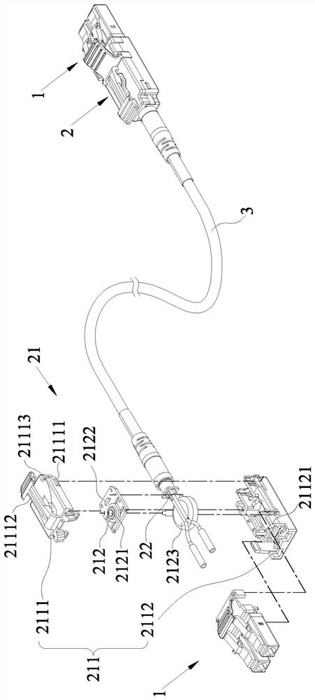
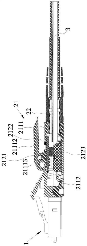
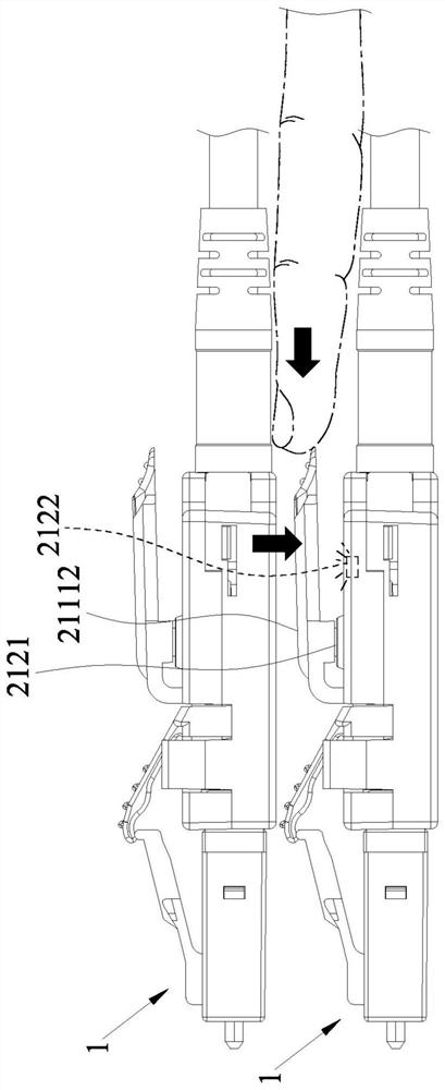
[0019] see figure 1 , figure 2 , image 3 , are the structural schematic diagram and combined cross-sectional view of the preferred embodiment of the present invention, as well as the state schematic diagram during operation. As shown in the following figures, the light-emitting tracking device 2 of the optical fiber connector 1 of the present invention includes a pair of operation units 21 and a signal line 22 , wherein the two optical fiber connectors 1 are connected to each other by an optical fiber cable 3 .

[0020] Each of the operating units 21 includes a casing 211 and a control circuit board 212 , and each casing 211 is extended to the rear end of each optical fiber connector 1 , so that the optical fiber cables 3 are respectively connected from the two operating units. 21, the control circ...


PUM


Abstract

The invention provides a light-emitting tracking device for an optical fiber connector, which includes a pair of operation units and a signal line. Each of the operating units is respectively disposed at the rear end of an optical fiber connector at the two ends of the same optical fiber cable, so that the optical fiber cables are respectively protruded from the two operating units, and each operating unit is internally provided with a control circuit board, and complete the electrical connection of the two control circuit boards through the signal line, each control circuit board is provided with a button, an LED, and a built-in power source is provided in the operation unit, and the shell is provided with a built-in power source. There is an extension lever on the surface corresponding to each button. By operating the extension lever on either side to press the corresponding button, the built-in power source can drive the LEDs inside the two operating units at the same time. Lights up to improve the operator's identification efficiency during jumper operations.

Description

technical field [0001] The invention relates to the field of network communication equipment, in particular to a light-emitting tracking device for an optical fiber connector. When the optical fiber connector is inserted into a corresponding device, it only needs to operate the operating unit on either side to drive the two operating units synchronously. The internal LED lights up at the same time to improve the operator's identification efficiency during jumper operation. Background technique [0002] The network cable used in the general network system is not only used as the connection between the general personal computer and the network socket on the wall, but also often used in the construction of the network computer room and the network wiring of the building. These network cables are generally wired with open wires. Usually, the number of such network information sockets will not exceed six at most. Therefore, when there is a problem with the network, for example, t...

Claims


Application Information

Patent Timeline
Patent Type & Authority Patents(China)
IPC IPC(8): G02B6/38
CPCG02B6/3895
Inventor 林宴临
Owner JYH ENG TECH
Why Eureka
Try Eureka