Method and apparatus for air extraction in the area of a heating press

An air suction, hot press technology, applied in cleaning methods and utensils, chemical instruments and methods, applications, etc., can solve problems such as energy loss

Pending Publication Date: 2020-09-29
HARBURG FREUDENBERGER MASCHENBAU
View PDF9 Cites 1 Cited by
  • Summary
  • Abstract
  • Description
  • Claims
  • Application Information

AI Technical Summary

Problems solved by technology

[0008] The methods and devices according to the prior art lead, on the one hand, to the release of harmful substances into the environment before they are discharged or aspirated.
Furthermore, on the other hand a huge energy loss in the form of heat generated to the environment

Method used


Image

  • Method and apparatus for air extraction in the area of a heating press
  • Method and apparatus for air extraction in the area of a heating press
  • Method and apparatus for air extraction in the area of a heating press

Examples


Embodiment Construction

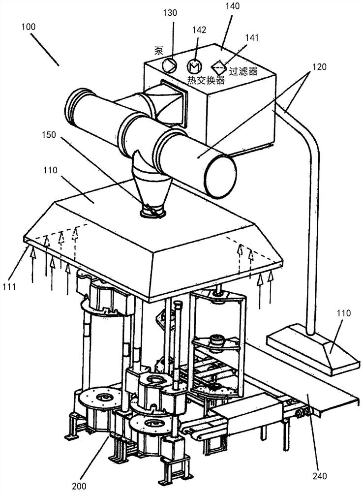
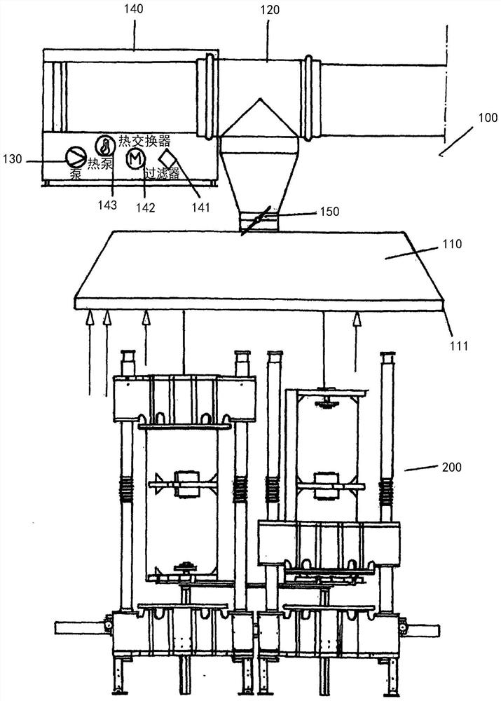
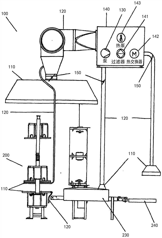
[0080] According to the device (100) according to the invention for air suction in figure 1 In the embodiment shown three-dimensionally, the suction takes place above and / or next to or behind the tire heat press (200). The tire heat press (200) is configured as a double tire heat press.

[0081] The device (100) for air suction has two suction devices (110) configured as suction guards, which are connected via a suction tube (120) to an air delivery device (130) configured as a pump. )connect.

[0082] In the region of the suction device ( 110 ), suction openings ( 111 ), which are designed, for example, as suction slits running around on the outer edge of the suction device ( 110 ), are arranged below.

[0083] In the joint area of ​​the suction pipe (120) on the suction device (110) arranged centrally above the tire heat press (200), a flap (150) is arranged in the suction pipe (120), wherein , the suction tube (120) can be gradually opened and closed by means of the posi...


PUM


Abstract

The method and the apparatus serve for air extraction (100) in the area of a heating press (200). Extracted air is fed to at least one exhaust-air treatment device (140). In the area of the device, the extracted air is modified in terms of at least one parameter. It is intended in particular to use a tyre heating press (200) as the heating press.

Description

technical field [0001] The invention relates to a method for air suction in the region of a heat press, in which method the suctioned air is supplied to at least one device for applying the suctioned air. [0002] The invention also relates to a device for air suction in the region of a heat press, said device being provided with means for applying the suctioned air. [0003] In particular, the invention relates to a tire heating press equipped with a device for air suction. Background technique [0004] To vulcanize green tires, a tire heat press is used. A tire heat press typically has a mold into which the tire to be vulcanized is loaded. Due to the manual handling of green and vulcanized tires and due to the vulcanization process large quantities of gases and particles are released and emitted. These gases are warm or even hot on the one hand and, on the other hand, often contain a series of potentially harmful components for the environment and / or for health. [000...

Claims


Application Information

Patent Timeline
Patent Type & Authority Applications(China)
IPC IPC(8): B08B15/02B29D30/06B08B15/00
CPCB08B15/002B08B15/02B29D30/0601B29D30/0662B29D2030/0677
Inventor A·施特曼F·埃尔德曼
Owner HARBURG FREUDENBERGER MASCHENBAU
Why Eureka
Try Eureka