Actuation system and clutch device for a motor vehicle

A control system and clutch device technology, applied to mechanical drive clutches, non-mechanical drive clutches, motor vehicles, etc., can solve the problems of increased wear and tear of the moment of inertia, and achieve the effect of saving structural space

Active Publication Date: 2019-05-03
SCHAEFFLER TECH AG & CO KG
View PDF8 Cites 0 Cited by
  • Summary
  • Abstract
  • Description
  • Claims
  • Application Information

AI Technical Summary

Problems solved by technology

A disadvantage of these known embodiments is that these spring devices require additional radial installation space and since the spring device is arranged in or on the rotational region of the c...

Method used


Image

  • Actuation system and clutch device for a motor vehicle
  • Actuation system and clutch device for a motor vehicle
  • Actuation system and clutch device for a motor vehicle

Examples


Embodiment Construction

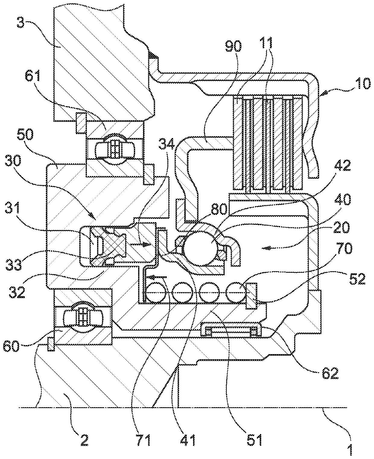
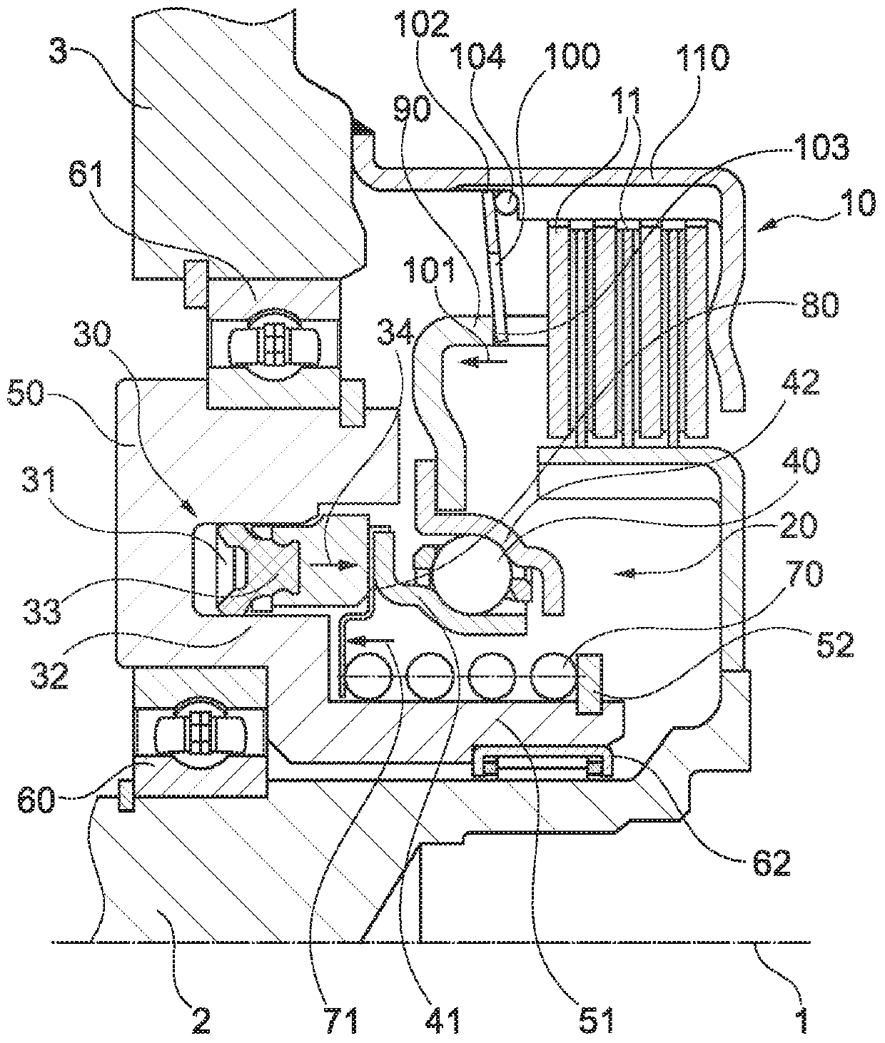
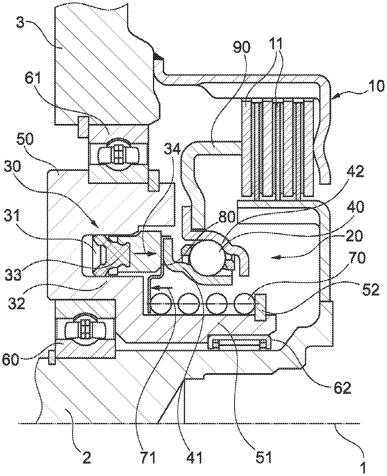
[0031] exist figure 1 A clutch device according to the invention of a simpler construction type is shown in , while in figure 2 A clutch arrangement according to the invention with an additional spring arrangement can be seen in . That is, in figure 1 The clutch device shown in is only supplemented with an additional spring device in the figure 2 shown in .

[0032] Firstly, the general structure of the clutch device according to the invention and the actuation system according to the invention is explained on the basis of two figures.

[0033] The actuation system 20 according to the invention and the clutch device 10 actuated thereby are arranged on a common axis of rotation 1 . The actuation system 20 comprises a piston-cylinder unit 30 , the piston 31 of which is displaceable substantially parallel to the axis of rotation 1 in a cylinder 32 , which is formed by a housing 50 . As a result, the piston 31 can exert an axial force in the acting direction 34 via the actu...


PUM


Abstract

The invention relates to an actuation system (20) for actuating a clutch (10), in particular a separating clutch of a motor vehicle, comprising a substantially annular piston/cylinder unit (30), the piston (31) of which can be moved along a working direction (34) in a substantially translational manner in an axial direction in order to actuate the clutch (10), and comprising an annular actuation bearing (40) which allows a relative rotational movement between the piston/cylinder unit (30) and the clutch (10) to be actuated. The actuation system further comprises a spring device (70) for providing a force (71) which acts in a substantially axial direction opposite the working direction (34) of the piston/cylinder unit (30), wherein the spring device (70) is supported against the non-rotating side (41) of the actuation system (20). By means of the aforementioned invention, an actuation system and a clutch device equipped with said actuation system are thus provided which combine a smallradial installation space with a long service life.

Description

technical field [0001] The invention relates to an actuation system for a clutch device, for example a clutch device for a hybrid module, which is provided for a motor vehicle, such as a passenger car, a van or another commercial vehicle, and is coupled to an internal combustion engine. The invention also relates to the clutch device itself, which has the actuation system. Background technique [0002] A hybrid module generally comprises: a coupling device for mechanically coupling the internal combustion engine; a disconnect clutch with which torque can be transmitted from the internal combustion engine to the hybrid module and with which the hybrid module can be decoupled from the internal combustion engine; an electric motor with for generating drive torque using the rotor; and a dual clutch arrangement by which torque can be transmitted from the electric machine and / or from the disconnect clutch to the drive train. The dual clutch device includes a first sub-clutch and ...

Claims


Application Information

Patent Timeline
IPC IPC(8): F16D25/08
CPCB60K6/387B60K6/40B60K6/48F16D13/52F16D25/10B60K2006/4825F16D2021/0661F16D2021/0676Y02T10/62F16D25/082F16D13/385F16D21/06F16D21/08F16D25/083F16D25/087
Inventor 德克·霍夫斯特
Owner SCHAEFFLER TECH AG & CO KG
Why Eureka
Try Eureka