Control device

A technology of a control device and a control mechanism, which is applied in the field of control clutches, can solve the problems of easy wear of the stop claw, increased cost, high cost, etc.

Inactive Publication Date: 2017-06-09
SCHAEFFLER TECH AG & CO KG
View PDF1 Cites 0 Cited by
  • Summary
  • Abstract
  • Description
  • Claims
  • Application Information

AI Technical Summary

Problems solved by technology

However, this design is very expensive in terms of the components used and the locking pawl is very prone to wear, which increases the cost

Method used


Image

  • Control device
  • Control device
  • Control device

Examples


Embodiment Construction

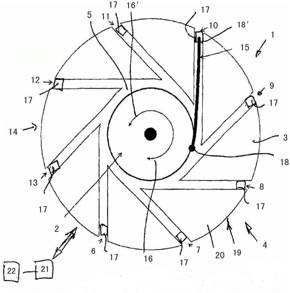
[0028] figure 1 An actuating device 1 is shown schematically, in particular for actuating a transmission for selecting a transmission stage and for engaging and / or disengaging a selected transmission stage and / or for actuating a clutch, for example for disabling a clutch Engage and / or disengage.

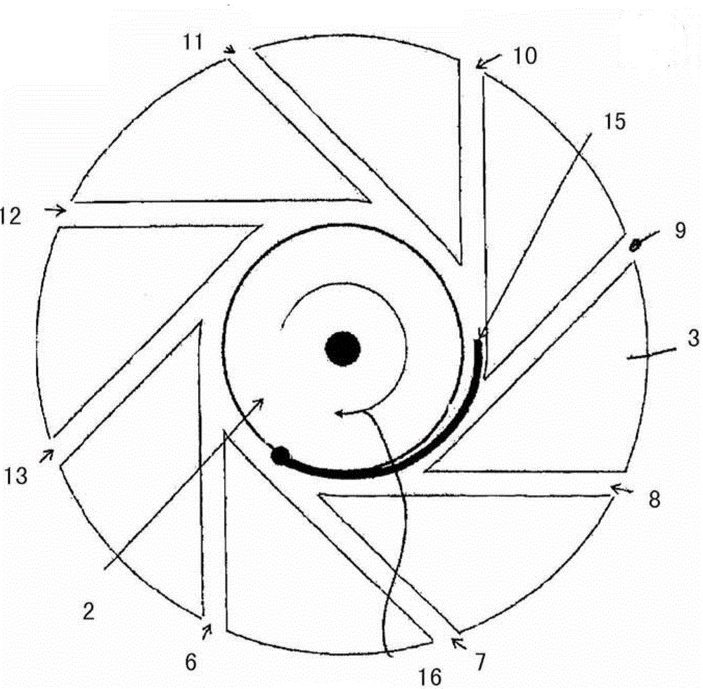
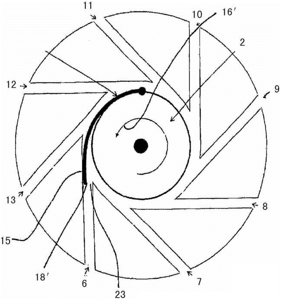
[0029] The handling device 1 is designed with a drive wheel 2 and a tunnel element 3 . The tunnel element 3 is designed here as an essentially annular element 4 with a central groove 5 . The groove 5 serves to accommodate the drive wheel 2 in the inner region of the tunnel element 3 .

[0030] The tunnel element 3 has a plurality of tunnels 6 , 7 , 8 , 9 , 10 , 11 , 12 and 13 . The lanes 6 , 7 , 8 , 9 , 10 , 11 , 12 and 13 extend radially outward from the radially inner central groove 5 to the outer edge of the lane element 3 .

[0031] The drive wheel 2 is preferably mounted rotatably about an axis 14 and has a slide 15 which is connected to the drive wheel 2 at an end region 18...


PUM


Abstract

The device (1) has a lane element (3) designed as an annular element (4) and provided with a central recess (5). Lanes (6-13) i.e. holes, radial outwardly extend from the central recess. A driving wheel (2) is received in the central recess and comprises a slider (15) that is insertable into the lanes. The lanes are selectable by a movement of the driving wheel in a rotation direction (16) relative to the lane element. The slider comprises a resilient and / or flexible slide element. The driving wheel and / or the lane element are rotatable by a drive motor (21). The driving wheel is designed as a cylindrical element or a disk-shaped element.

Description

technical field [0001] The invention relates to an actuating device, in particular for actuating a transmission for selecting a gear stage and for engaging and / or disengaging a selected gear stage and / or for actuating a clutch. Background technique [0002] In the vehicle transmission, the speed transmission between the transmission input shaft and the transmission output shaft is formed by a gear pair. Embodiments are known here, for example, as spur gear transmissions. The shifting of the transmission takes place here via a gearshift mechanism in the transmission. In a manually shifted transmission, the shifting mechanism is connected to a shift lever via a transmission rod or a cable drive. In automated transmissions, the shift mechanism is actuated by means of an actuating device with an actuator for selecting a transmission stage and an actuation for engaging and / or disengaging the selected transmission stage device. [0003] In the spur gear transmission described ...

Claims


Application Information

Patent Timeline
Patent Type & Authority Patents(China)
IPC IPC(8): F16H63/20
CPCF16H63/20F16H2063/202F16H61/32F16H2061/2838
Inventor D·赫尔科默
Owner SCHAEFFLER TECH AG & CO KG
Why Eureka
Try Eureka