Double bottom element for double bottom

A double-component technology, which is applied in the assembly field of multiple double-bottom components, can solve the disadvantages of dismantling and rebuilding the production system, and achieve the effect of minimizing time and operation cost and flexible production mechanism

Pending Publication Date: 2020-06-05
ROBERT BOSCH GMBH
View PDF12 Cites 0 Cited by
  • Summary
  • Abstract
  • Description
  • Claims
  • Application Information

AI Technical Summary

Problems solved by technology

The question of dismantling and rebuilding is especially detrimental for production systems of defined size (power, weight, dimensions) and functionality

Method used


Image

  • Double bottom element for double bottom
  • Double bottom element for double bottom
  • Double bottom element for double bottom

Examples


Embodiment Construction

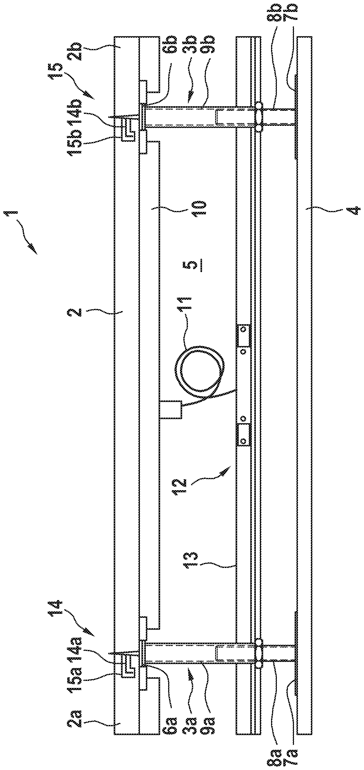
[0046] according to figure 1 , the double bottom element 1 consists of an upper bottom plate 2 which rests at the top corners on a frame element 3 which is designed with brackets 3a, 3b, for example metal brackets, by means of which the bottom plate 2 is supported on a primary bottom, for example concrete 4 above. The base plate 2 is arranged at a distance from the original base 4 by means of the supports 3 a , 3 b , so that a free space 5 (interspace) is formed between the original base 4 and the base plate 2 and delimited by the frame elements 3 . The supports 3 a and 3 b have a top plate 6 a or 6 b for supporting the top corners of the base plate 2 and have a foot plate 7 a or 7 b with which the supports 3 a and 3 b rest on the original base 4 . The brackets 3a, 3b are preferably height-adjustable, for example via threaded rods 8a or 8b on the foot plate 7a or 7b, which are inserted into threaded tubes 9a or 9b on the top plate 6a or 6b.

[0047] according to figure 1 Th...


PUM


Abstract

The invention relates to a double bottom element (1) for a double bottom (58). The double bottom element (1) at least comprises an upper base plate (2), a defined free space (5) connected downward tothe upper base plate, at least two functional elements (54, 55, 56, 57), and at least one connecting element (14, 15) for connecting at least one other double base element (1a to 1n), wherein the at least one functional element (54, 55, 56, 57) can be actuated by a controller (34, 35).

Description

technical field [0001] The invention relates to a double bottom element for a double bottom. The double bottom element is especially equipped with integrated additional functions. Furthermore, the invention includes the assembly of multiple double bottom elements. Background technique [0002] In particular in industrial buildings a floor construction commonly referred to as a "double bottom" is used. In the case of a double bottom, plates placed on supports are arranged above the existing sole or above a solid original roof, which can consist, for example, of concrete. For a further introduction to this common structure of double bottoms see, for example, DE 20 2007 017236 U1. The stand basically has a foot plate which rests on the bottom of the foot below or on top of the original roof. Double bottom-plate is removable. With the aid of the double floor, it is easy to equip and retrofit the building as required with lines for communication technology and electricity, s...

Claims


Application Information

Patent Timeline
Patent Type & Authority Applications(China)
IPC IPC(8): E04F15/024
CPCE04F15/024E04F15/02405E04F15/0247E04F15/02452H02J50/005H02J50/10
Inventor J.施蒂利希
Owner ROBERT BOSCH GMBH
Why Eureka
Try Eureka