Control system of engineering bridge transport vehicle

A technology for handling systems and transport vehicles, which is applied in the directions of transportation and packaging, special positions of vehicles, and vehicles used to carry long goods, etc. Convenience and other issues

Active Publication Date: 2012-12-26
SHAANXI TONLY HEAVY IND
View PDF0 Cites 0 Cited by
  • Summary
  • Abstract
  • Description
  • Claims
  • Application Information

AI Technical Summary

Problems solved by technology

Difficulty in beam transportation and poor manoeuvrability
[0004] 2. The traditional engineering bridge transport vehicle, clutch control, adopts one-way control. When the main vehicle and the auxiliary vehicle participate in the transport bridge operation at the same time, the auxiliary vehicle is running backwards, and the driver of the auxiliary vehicle is facing the driving direction. The rearview mirror of the vehicle observes the driving situation of the main vehicle in order to cooperate with the transport bridge. It is inconvenient to observe the main vehicle and cooperate with the driving, and there are potential safety hazards
[0005] 3. The traditional engineering bridge transport vehicle braking system adopts all-wheel driving brake and parking brake, and only supports one-way driving of the vehicle. When the main vehicle and the auxiliary vehicle are involved in transporting the bridge at the same time, the auxiliary vehicle is reversed. When driving, the driver of the co-driver faces the direction of travel, and uses the rearview mirror of the vehicle to observe the driving situation of the main vehicle in order to cooperate with the transport bridge. It is inconvenient to observe the main vehicle and cooperate with driving, and there are potential safety hazards

Method used


Image

  • Control system of engineering bridge transport vehicle
  • Control system of engineering bridge transport vehicle
  • Control system of engineering bridge transport vehicle

Examples


Embodiment 1

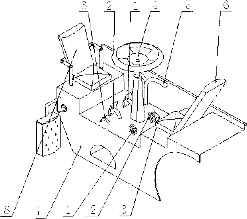
[0024] Embodiment 1: as figure 1 As shown, this engineering bridge transport vehicle control system includes a clutch control mechanism 1, a brake control mechanism 2, an accelerator control mechanism 3, a steering wheel 4, a speed change control mechanism 5 and a seat, and is characterized in that: clutch control mechanism 1, The brake control mechanism 2 and the accelerator control mechanism 3 are two-way operation structures, the steering wheel 4 is fixed on the control work platform 7, and the steering wheel 4 is fixed with a seat 6 for forward travel and a seat 8 for reverse travel symmetrically in the forward and reverse directions. The forward clutch pedal 2-4 of the clutch operating mechanism 1 is connected to the left bottom of the seat 6 for forward travel, and the reverse clutch pedal 2-3 of the clutch operating mechanism 1 is connected to the left side of the seat 8 for reverse travel. At the bottom of the side, the pedals of the two gas pedals 3 are respectively c...

Embodiment 2

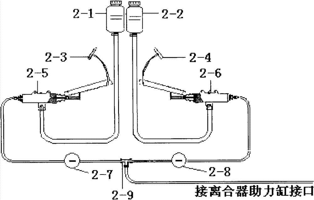
[0026] Embodiment 2 is basically the same as Embodiment 1, and the difference is that the manipulation of its clutch is as follows: Figure 2-1As shown, the two-way operation structure of the clutch operation mechanism 1 adopts a two-way operation mechanism with the same structure and symmetrical connection, which at least includes a reverse clutch pedal 2-3, a forward clutch pedal 2-4, a reverse operation liquid storage tank And pipeline 2-1, forward control liquid storage tank and pipeline 2-2, reverse control clutch master cylinder 2-5, forward control clutch master cylinder 2-6, reverse control manual control valve 2-7, Forward manipulation manual control valve 2-8, tee joint 2-9; forward manipulation fluid storage tank and pipeline 2-2 are connected to forward manipulation clutch master cylinder 2-6 with rubber hose and connector, forward manipulation The clutch pedal 2-4 is connected to the forward steering clutch master cylinder 2-6 with bolts, and at the same time, the...

Embodiment 3

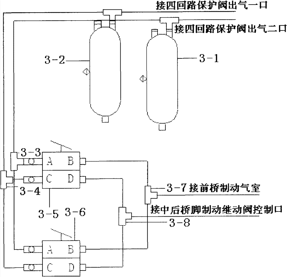
[0028] Embodiment 3 is basically the same as Embodiment 1, and the difference is that its braking system is as Figure 3-1 As shown, the two-way operation structure of the brake operating mechanism 2 includes at least forward and reverse brake pedals, a front axle brake air reservoir 3-1, a middle and rear axle brake control air reservoir 3-2, Three-way joint I 3-3, three-way joint II3-4, reverse brake master cylinder 3-5, forward brake master cylinder 3-6, two-way one-way valve I 3-7, two-way one-way valve II3- 8. The front axle brake air reservoir 3-1 is connected to the three-way joint I 3-3 through a connecting piece, and the other two ports of the three-way joint I 3-3 are respectively connected to the ports of the reverse brake master cylinder 3-5 A is connected to the port A of the forward master cylinder 3-6; the reverse foot brake pedal is connected to the reverse master cylinder 3-5, and the port B of the reverse master cylinder 3-5 is connected to the positive The ...


PUM


Abstract

The invention relates to a control system of an engineering bridge transport vehicle, in particular to a control system of an engineering bridge transport vehicle, which can realize the two-way running of the vehicle. The control system comprises a clutch control mechanism, a brake control mechanism, an accelerator control mechanism, a steering wheel, a variable speed control mechanism and seats, and is characterized in that the clutch control mechanism, the brake control mechanism and the accelerator control mechanism are two-way operation structures, the steering wheel is fixed on a control work platform, the seat for forward running and the seat for reverse running are symmetrically fixed in the forward direction and the reverse direction of the steering wheel, a forward clutch pedal of the clutch control mechanism is connected with the left bottom part of the seat for forward running, the reverse clutch pedal of the clutch control mechanism is connected with the left bottom part of the seat for reverse running, and two pedals of the accelerator control mechanism are respectively connected with the right bottom part of the seat for forward running and the right bottom part of the seat for reverse running. The invention realizes the two-way control of the bridge transport vehicle, thereby realizing the two-way running of the vehicle, enables the co-driver to face the running direction so as to improve the running safety, and makes the bridge transport vehicle realize the two-way brake control function, thereby realizing the two-way control of the bridge transport vehicle and two-way brake.

Description

technical field [0001] The invention relates to a control system of an engineering bridge transport vehicle, in particular to a control system of an engineering bridge transport vehicle capable of realizing two-way driving of the vehicle. Background technique [0002] At present, with the adjustment of national policies to stimulate domestic demand and accelerate infrastructure construction, the number and speed of construction of railway bridges, highway bridges and urban construction projects have increased. In the construction of such projects, the demand for bridge transport vehicles increases, especially domestic manufacturers of beam transport equipment with a load-bearing beam weight between 100 tons and 300 tons are almost blank. Most of the transportation of this kind of beams is made by some repair shops without design ability, according to the actual use requirements, to buy second-hand cars and restructure them. During the construction process, the main car and t...

Claims


Application Information

Patent Timeline
Patent Type & Authority Patents(China)
IPC IPC(8): B60P3/022B60N2/005B60K23/02B60K26/02B60T7/06
Inventor 董猛范翠玲吕彦明
Owner SHAANXI TONLY HEAVY IND
Why Eureka
Try Eureka