An underwater composite traffic tunnel

A composite and transportation technology, applied in the field of tunnel engineering, can solve problems such as waste, high construction cost, and limited underground resources, and achieve the effect of reducing transportation costs, reducing construction costs, and reducing the use of underground resources

Inactive Publication Date: 2017-09-29
HEFEI UNIV OF TECH
View PDF7 Cites 0 Cited by
  • Summary
  • Abstract
  • Description
  • Claims
  • Application Information

AI Technical Summary

Problems solved by technology

However, there is separation between different types of tunnels. Due to limited underground resources and high construction costs, building multiple different types of tunnels in a short distance will cause huge waste

Method used


Image

  • An underwater composite traffic tunnel
  • An underwater composite traffic tunnel
  • An underwater composite traffic tunnel

Examples


Embodiment Construction

[0020] The present invention will be further described through the embodiments below in conjunction with the accompanying drawings.

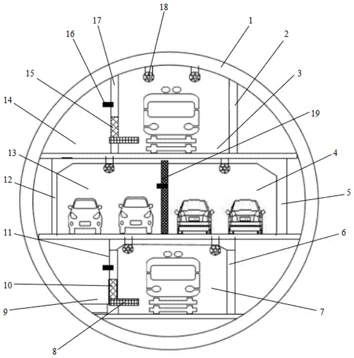
[0021] see figure 1 , an underwater composite traffic tunnel includes a shield tunnel 1, and the shield tunnel 1 is divided into three layers of lanes through three layers of lane plates from top to bottom, wherein the upper layer is the upper subway lane 3, the lower layer is the lower subway lane 7, and the middle layer For the roadway.

[0022] The upper floor subway lane 3 is a closed lane formed by the top wall of the upper floor left partition wall 17, the upper floor right partition wall 2 and the shield tunnel 1 on the first floor lane plate;

[0023] The lower floor subway lane 7 is a closed lane formed by the bottom wall of the lower floor left partition wall 11, the lower floor right partition wall 6 and the shield tunnel 1 on the third floor lane plate;

[0024] The upper subway lane 3 and the lower subway lane 7 realize the two-wa...


PUM


Abstract

The invention discloses an underwater composite traffic tunnel. The underwater composite traffic tunnel is composed of a double-layer subway line and a single-layer two-way highway. The underwater composite traffic tunnel comprises an upper-layer subway lane and a lower-layer subway lane; and according to a middle layer, a left side road traffic lane and a right side road traffic lane are formed by a middle-layer left partition wall and a middle-layer right partition wall between two layers of lane plates. The space formed by an upper-layer left partition wall, a lower-layer left partition wall and a shield tunnel is used for arranging an upper-layer evacuation exit and a lower-layer evacuation exit. The space formed by an upper-layer right partition wall, a lower-layer right partition wall and the shield tunnel is used for arranging tunnel ancillary facilities. A plurality of middle-layer escape doors are longitudinally arranged on the partition walls in the tunnel, and therefore when an accident happens, persons in the disaster traffic lanes can escape through the non-disaster traffic lanes. By means of the underwater composite traffic tunnel through which two-way driving of subways and automobiles can be achieved in a single-pipe tunnel, the utilizing rate of tunnel space is increased, construction cost is reduced, and soil resources are saved. Meanwhile, the passage pressure of existing bridge tunnels and roads is relieved.

Description

technical field [0001] The invention relates to the technical field of tunnel engineering, in particular to an underwater composite traffic tunnel. Background technique [0002] In recent years, the construction of shield tunnels has developed rapidly, and many types of tunnels have been designed in the limited space of shield tunnels. Among them, the construction of underwater double-layer highway tunnels and multi-layer tunnels has become a hot spot in recent years, such as Nanjing Weisan Road Crossing River Tunnel, Yangzhou Slender West Lake Tunnel, etc. With the further development of the economy in developed regions, more subway and road shield tunnels across the sea and river need to be built. Generally, shield tunnels are built with a double-pipe design to ensure the direction of coming and going. However, there is separation between different types of tunnels. Due to limited underground resources and high construction costs, building multiple different types of tunn...

Claims


Application Information

Patent Timeline
Patent Type & Authority Patents(China)
IPC IPC(8): E02D29/063E01C1/04
CPCE01C1/04E02D29/063
Inventor 唐飞梅凤珠李连健范传刚董满生石琴侯超群
Owner HEFEI UNIV OF TECH
Why Eureka
Try Eureka