Guide claw and method of arranging pump on base

A technology of guide claws and bases, applied in the direction of pump devices, components of pumping devices for elastic fluids, pumps, etc., can solve problems such as limited speed range, extra cost and downtime, limited energy saving, etc.

Pending Publication Date: 2022-01-11
GRUNDFOS HLDG
View PDF0 Cites 0 Cited by
  • Summary
  • Abstract
  • Description
  • Claims
  • Application Information

AI Technical Summary

Problems solved by technology

This can create reliability issues, causing additional costs and downtime
The usual way of overcoming this problem is to avoid the speed range where the resonance is excited, but this limits the speed range available and thus energy savings

Method used


Image

  • Guide claw and method of arranging pump on base
  • Guide claw and method of arranging pump on base
  • Guide claw and method of arranging pump on base

Examples


Embodiment Construction

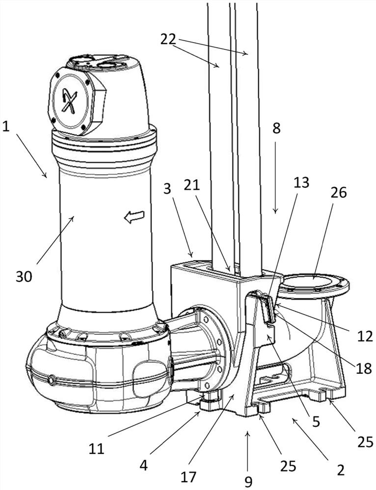
[0113] Refer to Figure 1. The figure shows a preferred embodiment of the pump support. The pump support may have a longitudinal direction, which in the embodiment shown is aligned with the flow direction of the tubing exiting the pump and entering the base.

[0114] The pump support as shown has a base portion 2 with a lower end 9 and an upper end 8, wherein the base portion 2 is configured for mounting the pump support at its lower end 9 to a surface such as a base plate. The pump support carries the member. In FIG. 1 , recesses 25 are provided for receiving bolts screwed into the carrier member to mount the base part 2 to the carrier member 10 . In some embodiments, an elastic element may be arranged between the base part 2 and the carrier member 10 .

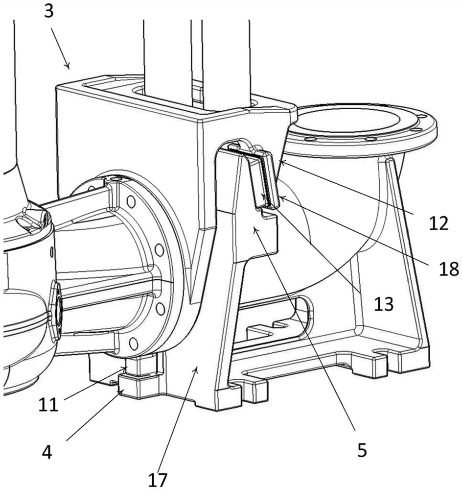
[0115] The base portion includes an end face 17 . As shown in Figure 5, the end face 17 forms an opening into the tubular section of the base part 2, which opening forms an inlet for the liquid received from the pump. Du...


PUM


Abstract

The invention relates to a guide claw and a method of arranging a pump on a base. In some particular preferred embodiments, the invention relates to the field of pumping stations for sewage and wastewater with submersible pumps mounted in the bottom of the wells. To allow easy cleaning and maintenance of the pumps without getting in contact with the sewage, the solution is a system for easy lifting the pump out of the well and lower it again called an auto coupling.

Description

technical field [0001] In some particularly preferred embodiments, the invention relates to the field of pumping stations for sewage and waste water with submersible pumps installed in the bottom of wells. In order to allow easy cleaning and maintenance of the pump without contact with sewage, the solution is a system for easily lifting the pump out of the well and lowering it again, which is called an autocoupling. [0002] Guide dogs are secured to the pump to guide the pump during lifting / lowering eg on a guide rod and to connect the pump to a base secured to the bottom of the well. In the lower position, the pump is rigidly connected to the base via guide claws in the upper and lower contact points, using gravity to generate the contact force. Lift pump unloads contact force. In order to support the pump in the transverse direction, the upper or lower contact point will be divided into two parts to receive reactions. Background technique [0003] In some practical imp...

Claims


Application Information

Patent Timeline
Patent Type & Authority Applications(China)
IPC IPC(8): F04D29/62F04D29/08F04D29/66
CPCF04D29/628F04D29/669F04D29/086F04D29/607F04D13/086F16M1/00F16M2200/08F16L23/18F04D3/00
Inventor P·霍夫曼
Owner GRUNDFOS HLDG
Why Eureka
Try Eureka