Parking lock for transmission comprising parking lock wheel

A technology for parking locks and transmissions, applied in the direction of elements with teeth, belts/chains/gears, mechanical equipment, etc., can solve the problems of cumbersomeness, consumption, and multi-structure space.

Active Publication Date: 2020-09-29
SCHAEFFLER TECH AG & CO KG
View PDF9 Cites 0 Cited by
  • Summary
  • Abstract
  • Description
  • Claims
  • Application Information

AI Technical Summary

Problems solved by technology

The guidance of the carriage or of the element actuating the locking pawl is cu

Method used


Image

  • Parking lock for transmission comprising parking lock wheel
  • Parking lock for transmission comprising parking lock wheel
  • Parking lock for transmission comprising parking lock wheel

Examples


Embodiment Construction

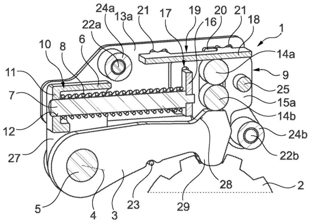
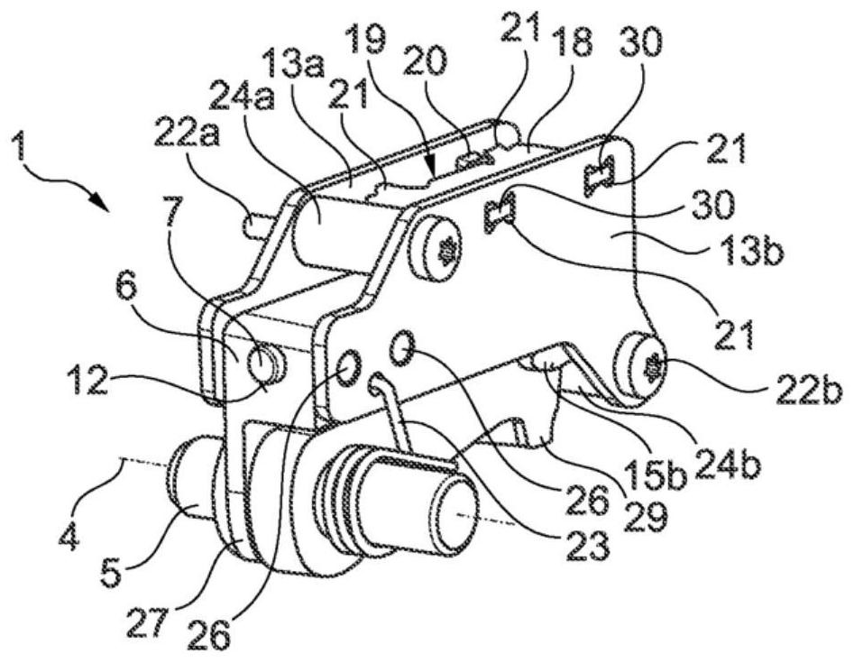
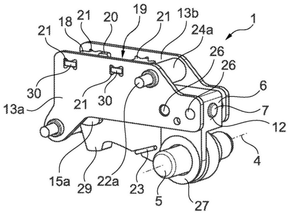
[0026] figure 1 , 2 and 3 show a parking lock 1 according to the invention for a—not shown in detail—transmission of a motor vehicle. From the transmission, figure 1 Only the parking lock wheel 2 is shown, wherein the locking pawl 3 of the parking lock 1 is currently shown engaged on the parking lock wheel 2 . Thus, the locking pawl 3 is shown in the locked position, wherein the locking pawl 3 engages in a tooth groove on the parking lock wheel 2 by means of the locking teeth 29 . The parking lock 1 - as presently shown - is pre-assembled as a unit and comprises: a locking pawl 3 which is pivotably accommodated on a bolt 5 about an axis of rotation 4; a carriage 9 which can be moved by - not shown here - the actuator actuates and is movable relative to the locking pawl 3 in the longitudinal direction of the locking pawl 3; and the guide rod 7 and the spring element 8, which Accommodated between carriage 9 and guide element 6 .

[0027]The guide element 6 is spatially arra...


PUM


Abstract

The invention relates to a parking lock (1) for the transmission of a motor vehicle, comprising a parking lock wheel (2). The parking lock comprises a pawl (3) which is designed to interact with the toothing of the parking lock wheel (2) in order to block the rotation of the parking lock wheel (2) in a locked position and to release the rotation of the parking lock wheel (2) in an unlocked position. The pawl (3) can be actuated via a slide (9) and is received on a pin (5) in a pivotal manner about a rotational axis (4), and a guide rod (7) and a spring element (8) are arranged on the slide (9). The slide (9) is operatively connected to the pawl (3) and can be moved axially in the longitudinal direction of the guide rod (7) in order to actuate the pawl (3). A guide element (6) is designed to guide the guide rod (7) and receive the spring element (8), and the guide element (6) has a casing (10) with a base (11), wherein the base (11) has a through-opening (12) for axially guiding the guide rod (7), and a first end section of the spring element (8) comes into contact with the base (11).

Description

technical field [0001] The invention relates to a parking lock for a transmission of a motor vehicle having a parking lock wheel. Background technique [0002] The parking lock is designed to engage with the locking pawl into the toothing of the parking lock wheel of the motor vehicle transmission when actuated by the driver of the motor vehicle, in order to block the transmission by said engagement of the locking pawl. The output shaft operatively connected to the parking lock wheel rotates, thereby preventing the motor vehicle from rolling. [0003] For example, a parking lock for an automatic transmission of a motor vehicle is known from DE 101 44 063 A1, which has a locking ring arranged on the transmission shaft and in the locked state of the device in the locking state of the locking ring. A pivotably supported pawl engaged in the locking recess. Furthermore, the parking lock has a likewise pivotably mounted selector lever which acts on a linkage which accommodates a...

Claims


Application Information

Patent Timeline
IPC IPC(8): F16H63/34
CPCF16H63/3425
Inventor 克劳斯·克拉默马蒂亚斯·费尔巴哈马库斯·罗斯特克里斯托夫·蒂劳夫托比亚斯·休曼
Owner SCHAEFFLER TECH AG & CO KG
Why Eureka
Try Eureka