Embossing machine for printing
A technology of embossing machine and embossing roller, which is applied to printing machines, rotary printing machines, printing, etc., can solve the problems of unclear printing embossing, achieve clear embossing printing, prevent unstable center of gravity, and ensure quality.
- Summary
- Abstract
- Description
- Claims
- Application Information
AI Technical Summary
Problems solved by technology
Method used
Image


Examples
Embodiment 1
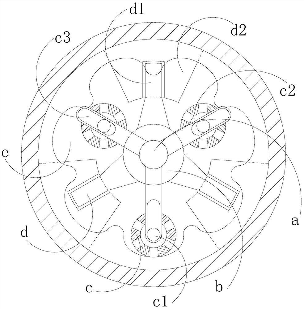
[0027] see Figure 1-Figure 6 , the present invention provides an embossing machine for printing, its structure includes a conveyor belt 1, an embossing roller 2, a control box 3, a frame 4, and a motor 5, the conveyor belt 1 is installed on the frame 4, and the conveyor The belt 1 is matched with the embossing roller 2, the embossing roller 2 is set on the machine base 4, the control box 3 is set on the side of the machine base 4, the bottom of the machine base 4 is set in a "U" shape, and the side The view is set up in a "convex" shape, and the motor 5 is installed directly below the position of the conveyor belt 1;
[0028] The embossing roller 2 is composed of a central shaft a, a shaft shifting chamber b, a counterweight mechanism c, a traction structure d, and a roller chamber e. The central shaft a is installed in the shaft shifting chamber b. The heavy mechanism c is connected, the traction structure d is installed in the roller chamber e, and the center of the roller...
Embodiment 2
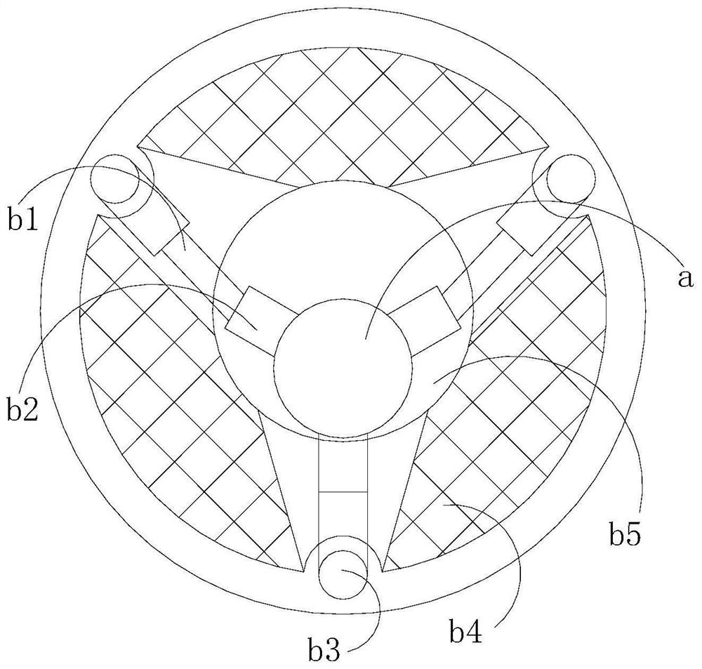
[0038] see Figure 1-Figure 2 , Figure 5 , the present invention provides an embossing machine for printing, its structure includes a conveyor belt 1, an embossing roller 2, a control box 3, a frame 4, and a motor 5, the conveyor belt 1 is installed on the frame 4, and the conveyor The belt 1 is matched with the embossing roller 2, the embossing roller 2 is set on the machine base 4, the control box 3 is set on the side of the machine base 4, the bottom of the machine base 4 is set in a "U" shape, and the side The view is set up in a "convex" shape, the motor 5 is installed directly below the position of the conveyor belt 1; the embossing roller 2 is composed of a central axis a, a shaft shift chamber b, a counterweight mechanism c, a traction structure d, and a roller chamber e The central shaft a is installed in the shaft shifting chamber b, the central shaft a is connected with the counterweight mechanism c, the traction structure d is installed in the roller chamber e, a...
PUM
 Abstract
Description
Claims
Application Information
 - R&D
- Intellectual Property
- Life Sciences
- Materials
- Tech Scout
- Unparalleled Data Quality
- Higher Quality Content
- 60% Fewer Hallucinations
Browse by: Latest US Patents, China's latest patents, Technical Efficacy Thesaurus, Application Domain, Technology Topic, Popular Technical Reports.
© 2025 PatSnap. All rights reserved.Legal|Privacy policy|Modern Slavery Act Transparency Statement|Sitemap|About US| Contact US: help@patsnap.com