Eureka AIR delivers breakthrough ideas for toughest innovation challenges, trusted by R&D personnel around the world.

Grid rudder and aircraft

A grid rudder and aircraft technology, applied in aircraft parts, aircraft control, transportation and packaging, etc., can solve the problems of low flight speed, inconspicuous aerodynamic heat problems, and no consideration of aerodynamic heat, etc.

Pending Publication Date: 2020-10-02
BEIJING XINGJI RONGYAO SPACE TECH CO LTD +1
View PDF7 Cites 4 Cited by
  • Summary
  • Abstract
  • Description
  • Claims
  • Application Information

AI Technical Summary

Problems solved by technology

[0003] The design of the existing grid rudder mainly considers the aerodynamic characteristics and structural strength, and does not consider the influence of aerodynamic and thermal problems
In the past, the working time of the grid rudder was short, the flight speed of the aircraft was low, and the problem of aerodynamic heat was not prominent

Method used


Image

  • Grid rudder and aircraft
  • Grid rudder and aircraft
  • Grid rudder and aircraft

Examples


Embodiment Construction

[0034] The technical solutions of the present invention will be clearly and completely described below in conjunction with the accompanying drawings. Apparently, the described embodiments are some of the embodiments of the present invention, but not all of them. Based on the embodiments of the present invention, all other embodiments obtained by persons of ordinary skill in the art without making creative efforts belong to the protection scope of the present invention.

[0035] In the description of the present invention, it should be noted that the terms "center", "upper", "lower", "left", "right", "vertical", "horizontal", "inner", "outer" etc. The indicated orientation or positional relationship is based on the orientation or positional relationship shown in the drawings, and is only for the convenience of describing the present invention and simplifying the description, rather than indicating or implying that the referred device or element must have a specific orientation, ...


PUM


Abstract

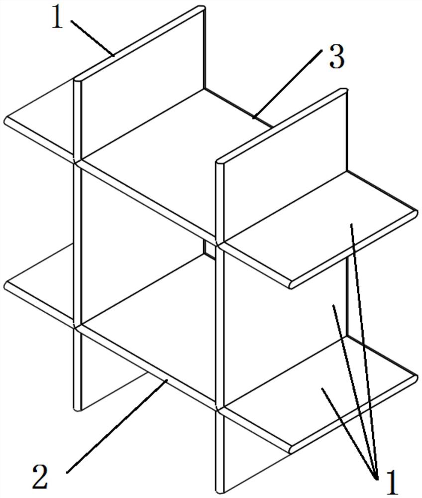
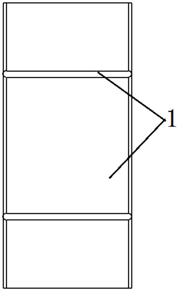
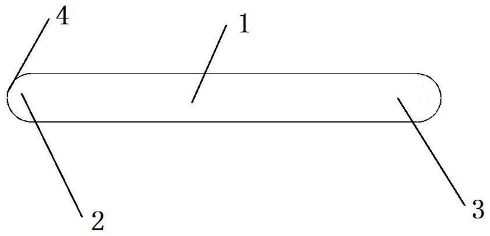
The invention provides a grid rudder and an aircraft. The grid rudder comprises a plurality of partition plates which are connected with each other and form a grid structure; wherein each partition plate is oppositely provided with a windward side and a leeward side along the two ends of the intersection line of the partition plates, at least one part of the windward side is provided with a notch,and the absolute value of the tangent slope of the outer surface where the notch is located is continuously reduced along the direction from the windward side to the leeward side, a flow guide curvedsurface is formed at the windward side, square arrangement at the windward side is avoided, and under hypersonic speed environment, on one hand, differential pressure resistance and friction resistance are reduced, power efficiency is improved, the total heat generated by heating of the windward side is reduced, and the structural strength of materials of the grid structure is guaranteed; on theother hand, the condition of local high heat generated by protruding parts such as edges and corners under the condition of airflow friction is improved, the aerodynamic heat of the grid structure isreduced, the thermal environment distribution of the grid structure is improved, and the temperature distribution uniformity is improved, so that the structural thermal stress is reduced, and the strength performance is optimized.

Description

technical field [0001] The invention relates to the technical field of aircraft design, in particular to a grid rudder and an aircraft. Background technique [0002] The grid structure is mainly used for air-to-air, surface-to-surface missiles and launch vehicle escape towers, as an aerodynamic stabilizer (grid wing) or control surface (grid rudder). [0003] The design of the existing grid rudder mainly considers the aerodynamic characteristics and structural strength, and does not consider the influence of aerodynamic and thermal problems. In the past, the working time of the grid rudder was short, the flying speed of the aircraft was low, and the problem of aerodynamic heat was not prominent. With the application of grid rudders on hypersonic vehicles and recoverable rockets, the flight speed has increased significantly, and the thermal environment problems of grid rudders have become increasingly prominent. Contents of the invention [0004] Therefore, the technical ...

Claims


Application Information

Patent Timeline
Patent Type & Authority Applications(China)
IPC IPC(8): B64C9/00
CPCB64C9/00
Inventor 彭小波郑立伟陈亮
Owner BEIJING XINGJI RONGYAO SPACE TECH CO LTD
Why Eureka
Eureka Blog
Learn More