Fluid heat exchange equipment

A technology of heat exchange equipment and fluid, which is applied to heat exchange equipment, lighting and heating equipment, heat exchanger shells, etc., and can solve problems such as the inability to utilize fluid kinetic energy, power waste of heat exchange equipment, and decreased heat exchange efficiency of equipment

Inactive Publication Date: 2020-10-02
顾艳波
View PDF8 Cites 3 Cited by
  • Summary
  • Abstract
  • Description
  • Claims
  • Application Information

AI Technical Summary

Problems solved by technology

[0002] In the field of fluid heat exchange, traditional heat exchange equipment has the phenomenon of power waste, and cannot use the kinetic energy generated by the fluid during the flow process, and after a long service life, the increase in pollutants will reduce the heat exchange efficiency of the equipment, so the designed This fluid heat exchange device

Method used


Image

  • Fluid heat exchange equipment
  • Fluid heat exchange equipment
  • Fluid heat exchange equipment

Examples


specific Embodiment approach 1

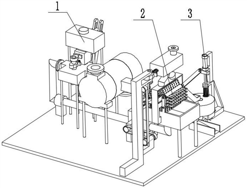
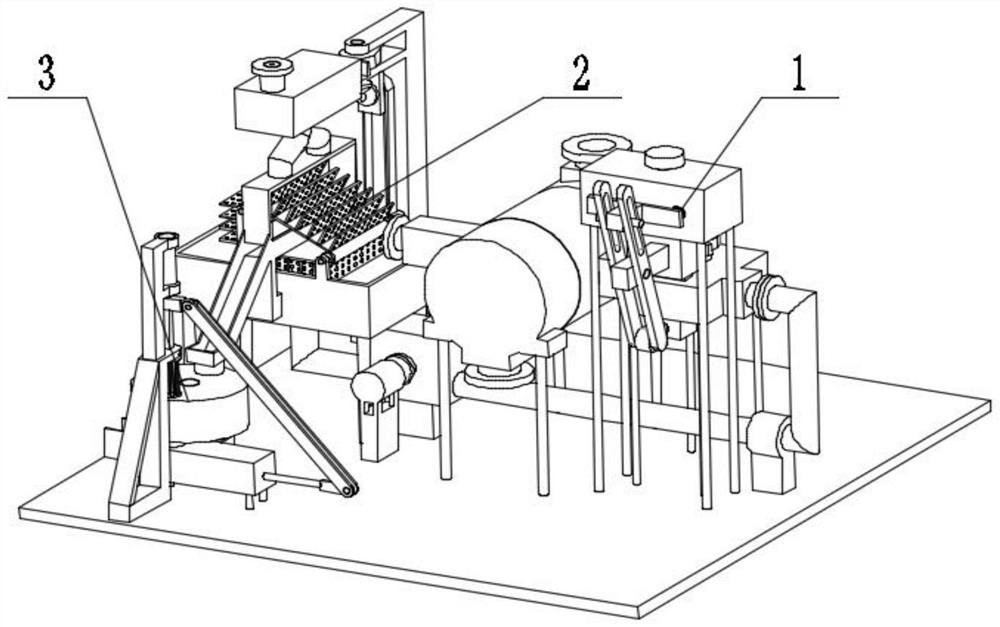
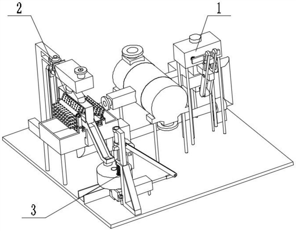
[0044] Combine below Figure 1 to Figure 28 Describe this embodiment. The present invention relates to a heat exchange device, more specifically a fluid heat exchange device, including a heat exchange mechanism 1, a filter mechanism 2, and a waste water treatment mechanism 3. The equipment can perform fluid heat exchange, and the equipment can The addition of ice cubes is realized by using fluid power, the equipment can filter the heat-exchanged water, and the equipment can clean the filter residue and squeeze the filter residue at the same time.

[0045] The heat exchange mechanism 1 is connected to the filter mechanism 2 , the filter mechanism 2 is connected to the waste water treatment mechanism 3 , and the waste water treatment mechanism 3 is connected to the heat exchange mechanism 1 .

specific Embodiment approach 2

[0047] Combine below Figure 1 to Figure 28 Describe this embodiment, this embodiment will further explain the first embodiment, the heat exchange mechanism 1 includes a base 1-1, a leg 1-2, a water inlet tank 1-3, a water inlet pipe with a flange 1- 4. Cam 1-5, camshaft 1-6, cam A1-7, passive seat with square column 1-8, ice cube transfer box 1-9, ice cube box 1-10, threaded plug 1-11, belt method Lan heat exchange inlet pipe 1-12, inlet box 1-13, heat exchange box 1-14, water outlet pipe 1-15, return water pipe with flange 1-16, water tank 1-17, motor base 1-18, support Leg A1-19, connecting seat with square column 1-20, waist groove 1-21, hinged arm 1-22, raised seat 1-23, hinged seat 1-24, hinged head 1-25, flange replacement Heat outlet pipe 1-26, buffer box 1-27, heat exchange connecting pipe 1-28, spring 1-29, outlet 1-30, connecting square pipe 1-31, stopper 1-32, communication groove 1-33 , sliding cavity 1-34, middle opening 1-35, stopper A1-36, connecting groove A...

specific Embodiment approach 3

[0049] Combine below Figure 1 to Figure 28 Describe this embodiment, this embodiment will further explain the first embodiment, the filter mechanism 2 includes a flange A2-1, a bent pipe 2-2, a pipe fixing seat 2-3, an acceleration box 2-4, and a box seat 2-5, bearing seat 2-6, pulley 2-7, belt 2-8, drive pulley 2-9, bearing seat A2-10, support seat A2-11, belt shaft drive pulley A2-12, belt A2-13 , passive pulley 2-14, cam I2-15, bearing seat I2-16, transmission shaft 2-17, bevel gear 2-18, belt shaft bevel gear 2-19, roller 2-20, filter plate 2-21, Roller A2-22, Roller B2-23, Belt B2-24, Coupling 2-25, Motor 2-26, Water Tank 2-27, Pressurizing Motor 2-28, Bearing Block II2-29, Coupling A2-30, water tank outrigger 2-31, driving water wheel 2-32, connecting shaft A2-33, launching check valve 2-34, connecting elbow 2-35, flange A2-1 and the inlet with flange The water pipes 1-4 are connected, the flange A2-1 is connected with the bent pipe 2-2, the bent pipe 2-2 is connected...


PUM


Abstract

The invention relates to heat exchange equipment, in particular to fluid heat exchange equipment. The equipment includes a heat exchange mechanism, a filtration mechanism, and a waste water treatmentmechanism, the equipment can carry out fluid heat exchange, can achieve the adding of ice cubes by utilizing fluid power, can filter water subjected to heat exchange, and can clean residue and meanwhile extrude the residue. The heat exchange mechanism is connected with the filtration mechanism, the filtration mechanism is connected with the waste water treatment mechanism, and the waste water treatment mechanism is connected with the heat exchange mechanism.

Description

technical field [0001] The invention relates to a heat exchange device, more specifically a fluid heat exchange device. Background technique [0002] In the field of fluid heat exchange, traditional heat exchange equipment has the phenomenon of power waste, and cannot use the kinetic energy generated by the fluid during the flow process, and after a long service life, the increase in pollutants will reduce the heat exchange efficiency of the equipment, so the designed This fluid heat exchange equipment. Contents of the invention [0003] The technical problem mainly solved by the present invention is to provide a kind of fluid heat exchange equipment, the equipment can perform fluid heat exchange, the equipment can use fluid power to realize the addition of ice cubes, the equipment can filter the water for heat exchange, and the equipment can clean the filter residue At the same time, the filter residue is squeezed. [0004] In order to solve the above technical problems...

Claims


Application Information

Patent Timeline
Patent Type & Authority Applications(China)
IPC IPC(8): F28D7/16F28F9/26B01D29/62B01D29/82B01D33/48B01D36/02F25C5/04F25D3/02B30B9/04
CPCB01D29/62B01D29/82B01D33/48B01D36/02B30B9/04F25C5/04F25D3/02F28D7/16F28F9/26
Inventor 顾艳波
Owner 顾艳波
Why Eureka
Try Eureka