
Nondestructive testing device for composite material

A non-destructive testing, composite material technology, applied in the direction of measuring devices, analytical materials, instruments, etc., can solve the problems of cumbersome, inconvenient, and single process, and achieve the effect of high flexibility, avoiding shaking or falling, and simple testing process.

Inactive Publication Date: 2020-10-02
浦江漱金电子科技有限公司
View PDF0 Cites 2 Cited by
  • Summary
  • Abstract
  • Description
  • Claims
  • Application Information

AI Technical Summary

Problems solved by technology

[0003] Traditional non-destructive testing equipment fixes the material to be tested on a movable frame, and then moves the frame to the bottom of the probe. This process requires fixing the material. The existing testing equipment is fixing the material It is inconvenient and cannot be adjusted according to the shape and size of the material to be tested. It is relatively simple. In addition, in order to detect the material to be tested in an all-round way, after the traditional equipment detects one side, the material needs to be disassembled again to detect the difference of the material. On the one hand, the process is more cumbersome, so we propose a non-destructive testing device for composite materials to solve the above problems

Method used


Image

  • Nondestructive testing device for composite material
  • Nondestructive testing device for composite material
  • Nondestructive testing device for composite material

Examples


Embodiment Construction

[0019] The following will clearly and completely describe the technical solutions in the embodiments of the present invention with reference to the accompanying drawings in the embodiments of the present invention. Obviously, the described embodiments are only some, not all, embodiments of the present invention.

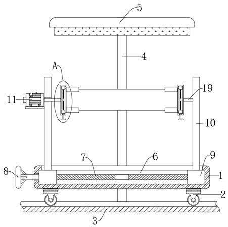
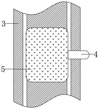
[0020] refer to Figure 1-4 , a non-destructive testing device for composite materials, comprising a fixed base 1, a plurality of pulleys 2 are fixedly installed on the side wall of the lower end of the fixed base 1, the lower ends of the plurality of pulleys 2 are jointly slidably connected with a slide rail 3, and the side walls of the slide rail 3 are fixed A connecting rod 4 is installed, and a probe 5 is fixedly installed on the upper end of the connecting rod 4. Through the setting of the pulley 2 and the slide rail 3, the fixed base 1 can be moved to the bottom of the probe 5 to realize the detection of materials;

[0021] The side wall of the fixed base 1 is ...


PUM


Abstract

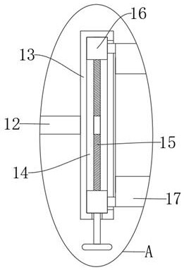
The invention discloses a nondestructive testing device for a composite material, and relates to the technical field of material detection. The device comprises a fixed base, a plurality of pulleys are fixedly mounted on the side wall of the lower end of the fixed base, the lower ends of the multiple pulleys are jointly connected with a sliding rail in a sliding mode, a connecting rod is fixedly mounted on the side wall of the sliding rail, and a probe is fixedly mounted at the upper end of the connecting rod. Through cooperative use of a first threaded rod, first threaded sleeves and supporting rods, the two first threaded sleeves can move towards each other or away from each other by rotating the first threaded rod, the distance between the two supporting rods can be adjusted, and materials with different lengths can be conveniently fixed; and through cooperation of a second threaded rod, second threaded sleeves and clamping plates, similarly, the distance between the two clamping plates can be adjusted by rotating the second threaded rod, so that the two ends of materials of different sizes are adjusted and fixed correspondingly, and the situation that the materials shake or fall off during detection and consequently normal detection is affected is avoided. Compared with traditional equipment, the flexibility is higher.

Description

technical field [0001] The invention relates to the technical field of material detection, in particular to a nondestructive detection device for composite materials. Background technique [0002] Non-destructive testing refers to the use of changes in thermal, sound, light, electricity, magnetic and other reactions caused by abnormal internal structures or defects of materials without damaging or affecting the performance of the tested object and the internal organization of the tested object. , by means of physical or chemical methods, with the help of modern technology and equipment, to inspect the structure, nature, state and type, nature, quantity, shape, position, size, distribution and changes of the internal and surface of the test piece And testing methods, non-destructive testing is an indispensable and effective tool for industrial development, to a certain extent, it reflects the level of industrial development of a country, and the importance of non-destructive ...

Claims


Application Information

Patent Timeline
IPC IPC(8): G01N33/00
CPCG01N33/00
Inventor 杨仲辉庄慧武张曼
Owner 浦江漱金电子科技有限公司
Learn More