Eureka AIR delivers breakthrough ideas for toughest innovation challenges, trusted by R&D personnel around the world.

A multi-channel dielectric loss measuring device and method

A loss measurement, multi-channel technology, applied in the field of multi-channel dielectric loss measurement devices, can solve problems such as multiple wiring

Active Publication Date: 2022-05-13
GUANGDONG POWER GRID CO LTD +1
View PDF12 Cites 0 Cited by
  • Summary
  • Abstract
  • Description
  • Claims
  • Application Information

AI Technical Summary

Problems solved by technology

[0004] The embodiment of the present invention provides a multi-channel dielectric loss measuring device and method, which solves the problem that multiple connections are required when testing a CVT in a substation

Method used


Image

  • A multi-channel dielectric loss measuring device and method
  • A multi-channel dielectric loss measuring device and method
  • A multi-channel dielectric loss measuring device and method

Examples


Embodiment 1

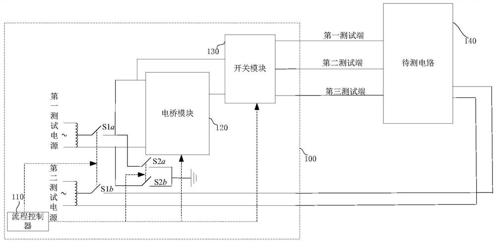
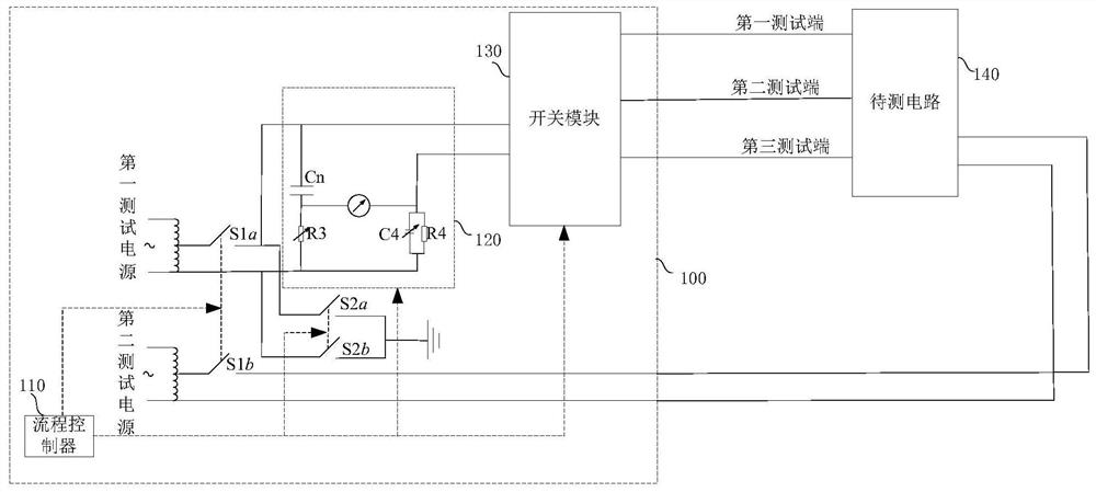
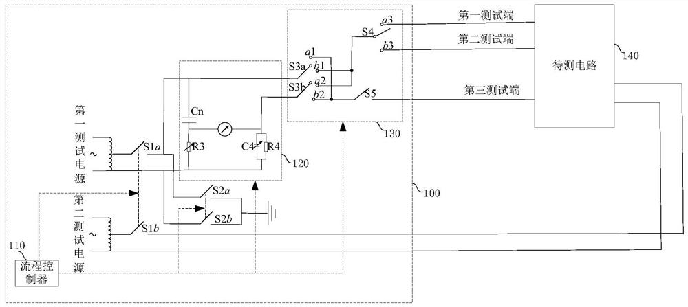
[0043] figure 1 It is a schematic diagram of a multi-channel dielectric loss measuring device in this embodiment, refer to figure 1, this embodiment provides a multi-channel dielectric loss measuring device 100 , including: a first test power supply, a second test power supply, a process controller 110 , a bridge module 120 , a first switch, a second switch, and a switch module 130 . The first end of the bridge module 120 is electrically connected to the first end of the first test power supply, and the second end is respectively connected to the first end of the switch module 130, the first end of the first unit S1a of the first switch, and the first end of the second switch. The first end of the first unit S2a is electrically connected, and the third end is electrically connected to the second end of the switch module 130 . The second end of the first test power supply is electrically connected to the second end of the first unit S1a of the first switch, and the first end i...

Embodiment 2

[0070] This embodiment provides a method for multi-channel dielectric loss measurement. The method of this embodiment can be performed by the multi-channel dielectric loss measurement device of the above-mentioned embodiment. The method also includes:

[0071] The process controller controls the on-off state of the first switch and the second switch and the conduction state of the first end, the second end and the first test end, the second test end and the third test end in the switch module, so that the circuit under test Different capacitors to be tested and the bridge module form a bridge circuit, and the capacitance value and dielectric loss value of the capacitor to be tested are calculated according to the bridge circuit.

[0072] Optionally, the process controller acquires the readings of the galvanometer, adjusts the values ​​of the adjustable resistors and capacitors, and calculates Capacitance value and dielectric loss value of the capacitor to be tested.

[0073] ...


PUM


Abstract

The embodiment of the present invention discloses a multi-channel dielectric loss measuring device and method, the device comprising: a first test power supply, a second test power supply, a process controller, a bridge module, a first switch, a second switch and a switch module; The process controller is used to control the on-off state of the first switch and the second switch and the conduction state of the first terminal and the second terminal and the first test terminal, the second test terminal and the third test terminal in the switch module, so that Different capacitors to be tested in the circuit to be tested and the bridge module form a bridge circuit, and the capacitance value and dielectric loss value of the capacitor to be tested are calculated according to the bridge circuit. The solution of the embodiment of the present invention solves the problem that multiple connections are required during the test of the capacitive voltage transformer used in the substation.

Description

technical field [0001] The invention relates to the field of electric power detection, in particular to a multi-channel dielectric loss measuring device and method. Background technique [0002] In recent years, with the improvement of residents' living standards and the establishment of major factories, the power consumption has risen sharply. The establishment of substations has alleviated the problem of large power consumption. Among them, capacitive voltage transformers (CVT) are commonly used equipment in substations. , consists of a capacitive voltage divider and an electromagnetic unit. [0003] In order to accurately evaluate the status of CVT equipment, electric maintenance personnel need to measure the capacitance of each section in the CVT separately. At present, the capacitance in the CVT equipment is measured through multiple wiring and multiple disassembly and assembly. This measurement method is cumbersome to operate. The measurement efficiency is low. Cont...

Claims


Application Information

Patent Timeline
Patent Type & Authority Patents(China)
IPC IPC(8): G01R27/26
CPCG01R27/2694G01R27/2605
Inventor 周佳王植魏东亮万四维薛峰陈世昌胡晓军陈家荣吴志彬陈冰心
Owner GUANGDONG POWER GRID CO LTD
Why Eureka
Eureka Blog
Learn More