Unlock instant, AI-driven research and patent intelligence for your innovation.
A network source steady-state reactive power coordination control method to improve the transient voltage stability level
What is Al technical title?
Al technical title is built by PatSnap Al team. It summarizes the technical point description of the patent document.
A technology of transient voltage stabilization and coordinated control, applied in the direction of AC network voltage adjustment, reactive power adjustment/elimination/compensation, reactive power compensation, etc., to improve the transient voltage stability level, reduce the amount of reactive power compensation, and reduce the amount of small effect
Active Publication Date: 2021-01-05
STATE GRID JIANGXI ELECTRIC POWER CO LTD RES INST +1
View PDF5 Cites 0 Cited by
Summary
Abstract
Description
Claims
Application Information
AI Technical Summary
This helps you quickly interpret patents by identifying the three key elements:
Problems solved by technology
Method used
Benefits of technology
Problems solved by technology
The contribution of this paper is to explain the correlation between the steady-state reactive power compensation method and the transient voltage stability level, but how to use the relevant conclusions to propose a network source steady-state reactive power coordination control strategy that is conducive to improving the transient voltage stability level remains to be seen. Continue to study
Method used
Image
Click on the blue label to locate the original text in one second.
Reading with bidirectional positioning of images and text.
Examples
Embodiment 1
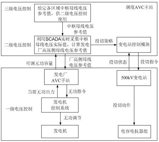
[0026] refer to Figure 1 to Figure 2 , a preferred embodiment of the present invention, a network source steady-state reactive power coordination control method for improving the transient voltage stability level, comprising the following steps:
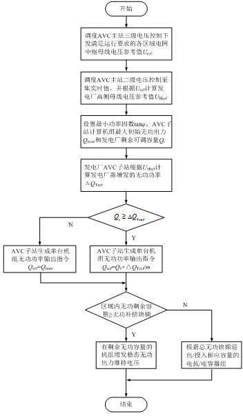
[0027] Step 1. Dispatch AVC main station three-level voltage control to issue central bus voltage reference value U ref For secondary voltage control use, U ref Given as a control parameter, let the allowable range of operating voltage of the central bus be [ U min , U max ], generally take U ref exist[ U min , 0.5 ( U min + U max )], when the actual value is taken, U ref The value is close to U min ;
[0028] Step 2: Scheduling the secondary voltage control of the AVC main station Collect the actual value of the central bus voltage and the reference value of the central bus voltage in real time through the SCADA system U ref Calculate the reference value of the busbar voltage on the high voltage side of the ste...
Embodiment 2
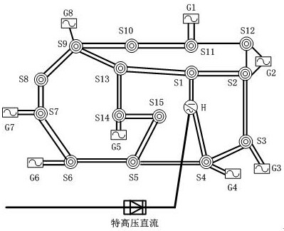
[0038] refer to Figure 3 to Figure 4 , the primary system wiring mode of the regional power grid in this embodiment is as follows image 3 As shown, S1-S15 in the figure are 15 500kV substations, each substation is equipped with 4 sets of low-voltage capacitors and 4 sets of low-voltage reactors; G1-G8 are 8 power plants, and H is an UHV DC converter station, considering the grid operation During load peaks, all gensets run at full capacity.
[0039] (1) The rated voltage of the central busbar is 525kV, and the allowable range during normal operation is [500, 550]kV, which is taken in this embodiment U ref =515kV.
[0040] (2) Calculate the reference value of the busbar voltage on the high-voltage side of the step-up transformer of the power plant G1~G8 U Href , respectively 516.3kV, 517.9kV, 516.7kV, 515.9kV, 516.1kV, 517.4kV, 521.8kV, 518.3kV.
[0041] (3) Set the maximum initial reactive power output coefficient of the generator in the AVC substation of the power pla...
PUM
Abstract
The invention relates to the technical field of automatic voltage control of power systems, particularly relates to a network source steady-state reactive coordination control method for improving thetransient voltage stability level. The method is based on a soft partition three-level voltage control architecture, and is characterized in that third-stage voltage control directly give a low voltage value in an allowable operation range to serve as a pivot bus voltage reference value, second-stage voltage control collects the actual values of the pivot bus voltage in each area in real time, takes the difference between the actual value and a reference value as input to obtain a bus voltage reference value of a high-voltage side of each power plant, a power plant AVC substation sets a steady-state reactive power output range of an unit, and during first-stage voltage control, if the reactive power regulation capacity of the unit is sufficient, transformer substation control in the second-stage voltage control is not started, and if the regulation capacity is insufficient, the unit outputs according to the maximum steady-state reactive power output, and the second-stage voltage control generates and executes a transformer substation capacitive reactance switching strategy in an area according to the reactive power vacancy. According to the invention, the reactive compensation proportion of a power generator can be increased, and the reactive compensation proportion of a capacitor can be reduced.
Description
technical field [0001] The invention relates to the technical field of automatic voltage control of electric power systems, in particular to a network source steady-state reactive power coordination control method for improving the transient voltage stability level. Background technique [0002] The scale of UHVDC connected to the power grid continues to grow, the characteristics of power electronics in the power system are becoming more and more obvious, the system damping level and voltage stability level are weakened, and the AC system failure is likely to cause DC commutation failure, resulting in huge fluctuations in the active and reactive power of the grid. For the weak DC receiving-end grid, the voltage stability problem under the impact of large disturbances is the main reason for restricting the transmission and consumption of DC power. How to improve the voltage stability of the DC receiving-end grid has become a hot spot for the current AC-DC hybrid grid. with fo...
Claims
Application Information
Patent Timeline
Application Date:The date an application was filed.
Publication Date:The date a patent or application was officially published.
First Publication Date:The earliest publication date of a patent with the same application number.
Issue Date:Publication date of the patent grant document.
PCT Entry Date:The Entry date of PCT National Phase.
Estimated Expiry Date:The statutory expiry date of a patent right according to the Patent Law, and it is the longest term of protection that the patent right can achieve without the termination of the patent right due to other reasons(Term extension factor has been taken into account ).
Invalid Date:Actual expiry date is based on effective date or publication date of legal transaction data of invalid patent.
