Supercharge Your Innovation With Domain-Expert AI Agents!

Latch fastener structure on concrete wedge block casting mould

A technology for pouring molds and concrete, applied in the directions of molds, mold fixtures, mold auxiliary parts, etc., can solve problems such as easy loss, and achieve the effect of convenient combination and disassembly

Inactive Publication Date: 2020-10-09
东莞市至简机电工程技术有限公司
View PDF0 Cites 3 Cited by
  • Summary
  • Abstract
  • Description
  • Claims
  • Application Information

AI Technical Summary

Problems solved by technology

Attachments currently exist figure 1 The block pouring mold shown, the mold includes a supporting channel steel 1, a supporting plate 2 is fixed on the supporting channel steel 1, a left formwork 3 and a right formwork 4 are respectively arranged on both sides of the supporting plate 2, and the two sides of the right formwork 4 The end is formed with a vertical slot 41, and a sealing baffle 5 is inserted into the slot 41. The sealing baffle 5 is fixed on the left template 3, and the sealing baffle 5 is provided with a support ear 52'. The ear 52' ​​passes through the right template 4 and inserts the positioning pin 14 for fixed positioning. The positioning pin 14 needs to be inserted and pulled out when the mold is assembled or disassembled. The 4 positioning pins are small and are often lost, so the positioning pin needs to be designed on the mold 14 will not break away from the lost structure

Method used


Image

  • Latch fastener structure on concrete wedge block casting mould
  • Latch fastener structure on concrete wedge block casting mould
  • Latch fastener structure on concrete wedge block casting mould

Examples


Embodiment Construction

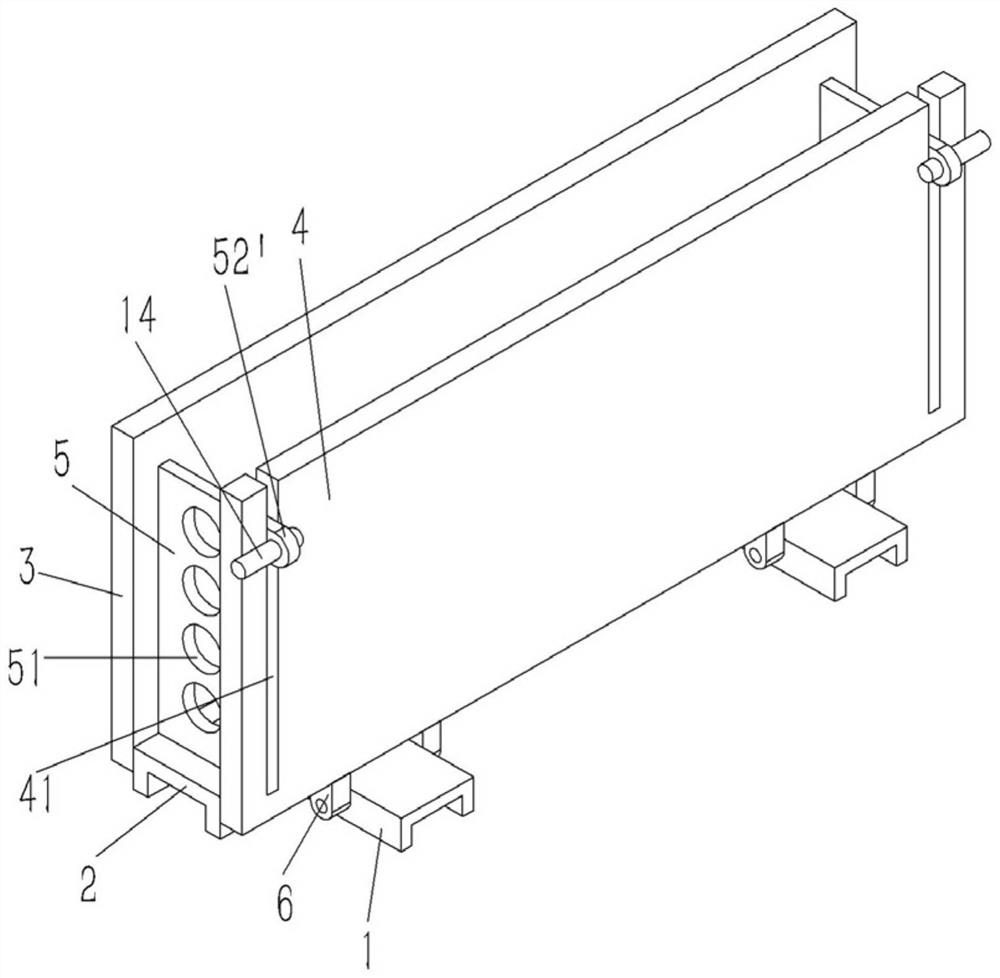
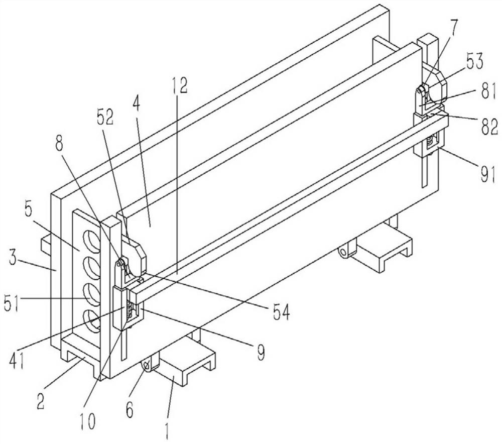
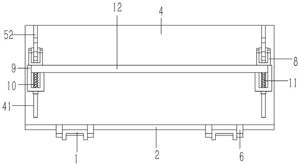
[0020] Example: see Figures 2 to 4 As shown, a locking structure on a concrete wedge pouring mold includes several horizontal support channel steels 1, the middle part of the support channel steel 1 is fixed with a longitudinal supporting plate 2, and the two sides of the supporting plate 2 are respectively provided with There are a left formwork 3 and a right formwork 4, and the lower end surfaces of the left formwork 3 and the right formwork 4 are fixed with hinge lugs 6, and the hinge lugs 6 are hinged with the supporting channel steel 2 through hinge shafts; Vertical slots 41 are formed at both ends, and a sealing baffle 5 is inserted into the slot 41. The sealing baffle 5 is fixed on the left template 3, and a support plate 52 is formed on the side wall of the upper end of the sealing baffle 5. The support plate The lower end surface of the 52 is formed with a vertical draw-in groove 53, and a pin shaft 7 is inserted in the draw-in slot 53. A slide block 8 is provided on...


PUM


Abstract

The invention discloses a latch fastener structure on a concrete wedge block casting mould. The latch fastener structure on the concrete wedge block casting mould comprises a plurality of horizontal bearing channel steel, a support plate, a left mould plate, a right mould plate and a seal baffle plate. The seal baffle plate is fixed onto the left mould plate; a bracket plate is formed on the sidewall of the upper end of the seal baffle plate; a vertical clamping groove is formed in the lower end face of the bracket plate; a pin shaft is inserted into the clamping groove; a sliding block is arranged on the lower side of the pin shaft; hinged supports are arranged on two sides of the upper end of the sliding block; support shafts are formed at two ends of the pin shaft; the support shafts on the pin shaft are inserted into the hinged supports; two sides of the sliding block are inserted into a groove rail with an L-shaped cross section; the groove rail is fixed onto the outer wall of the right mould plate; a support bottom plate is formed at the lower end of the groove rail; a vertical bolt is inserted onto the support bottom plate and penetrates through the support bottom plate soas to be screwed into the sliding block; a pressure spring is inserted onto the bolt in a sleeving way; and two ends of the pressure spring are pressed against the support bottom plate and the slidingblock.

Description

technical field [0001] The invention relates to the technical field of building material preparation devices, in particular to a locking structure on a concrete wedge casting mold. Background technique [0002] Concrete hollow blocks are made of ordinary concrete materials such as cement, sand, and stone. It is suitable for all kinds of building walls in areas with a building earthquake design intensity of 8 degrees and below, including high-rise and long-span buildings. Attachments currently exist figure 1 The block pouring mold shown, the mold includes a supporting channel steel 1, a supporting plate 2 is fixed on the supporting channel steel 1, a left formwork 3 and a right formwork 4 are respectively arranged on both sides of the supporting plate 2, and the two sides of the right formwork 4 The end is formed with a vertical slot 41, and a sealing baffle 5 is inserted into the slot 41. The sealing baffle 5 is fixed on the left template 3, and the sealing baffle 5 is pro...

Claims


Application Information

Patent Timeline
IPC IPC(8): B28B7/00B28B7/22
CPCB28B7/0014B28B7/22
Inventor 陆建友
Owner 东莞市至简机电工程技术有限公司
Features
  • R&D
  • Intellectual Property
  • Life Sciences
  • Materials
  • Tech Scout
  • Unparalleled Data Quality
  • Higher Quality Content
  • 60% Fewer Hallucinations
Learn More