
A new energy vehicle pedal

A new energy vehicle, pedal technology, applied in the direction of foot start device

Active Publication Date: 2021-08-20
玉环辰芯科技有限公司
View PDF0 Cites 0 Cited by
  • Summary
  • Abstract
  • Description
  • Claims
  • Application Information

AI Technical Summary

Problems solved by technology

[0005] The purpose of the present invention is to provide a new energy vehicle pedal to solve the problem that the existing new energy vehicle pedal cannot be structurally adjusted according to the braking situation to meet various braking needs

Method used


Image

  • A new energy vehicle pedal
  • A new energy vehicle pedal
  • A new energy vehicle pedal

Examples


Embodiment

[0073] In order to make the technical means, creative features, goals and effects achieved by the present invention easy to understand, the present invention will be further elaborated below in conjunction with illustrations and specific embodiments.

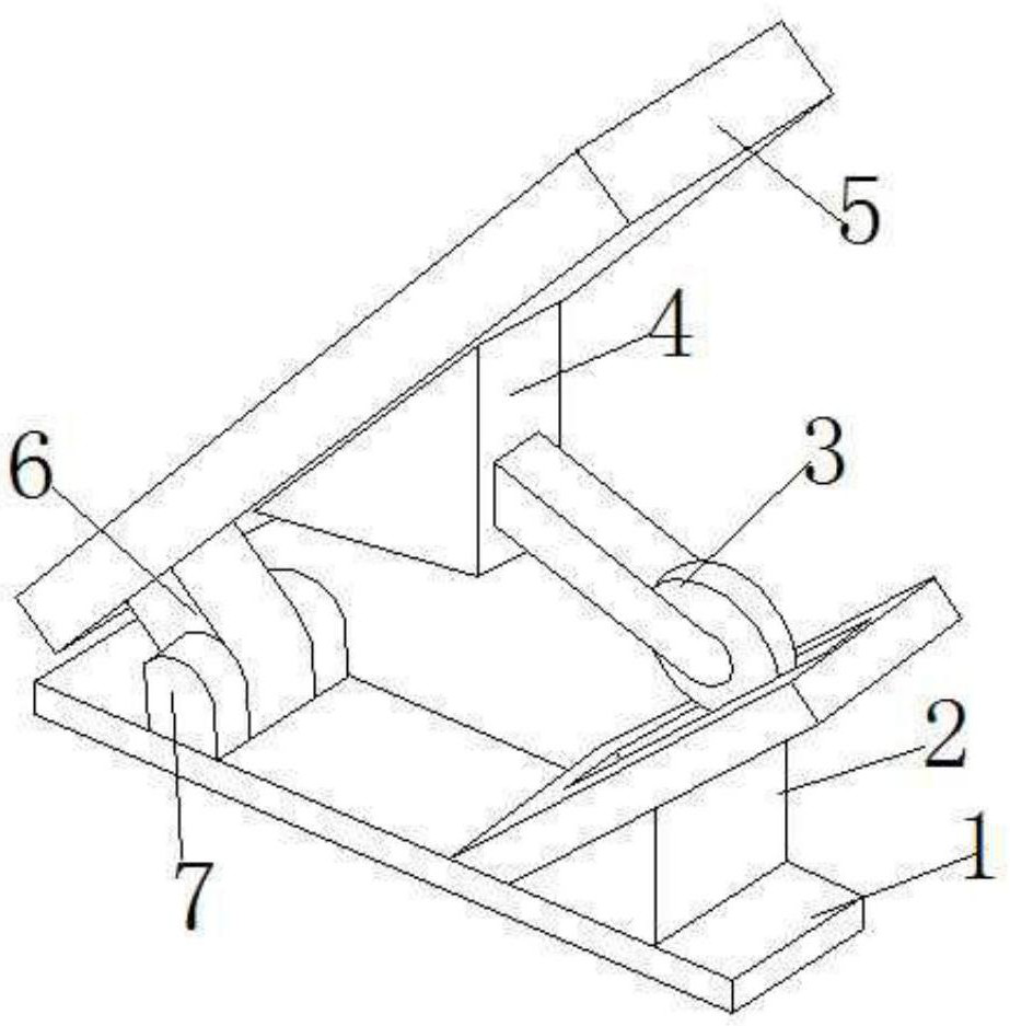
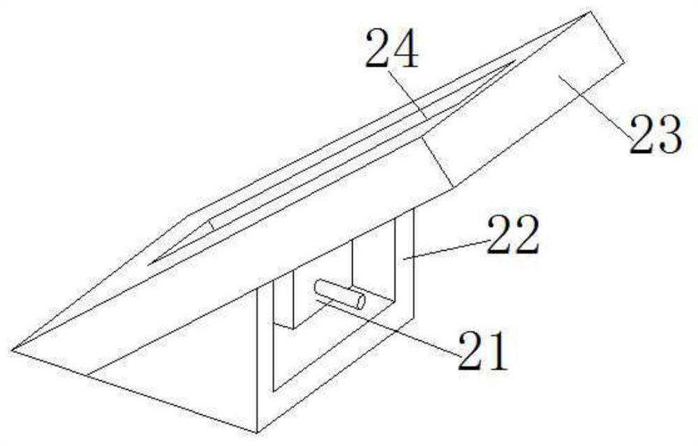
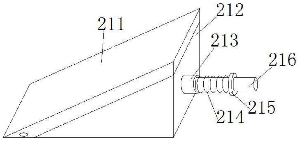
[0074] combine Figure 1 to Figure 15 The new energy vehicle pedal of the present invention will be described in detail.

[0075] The new energy vehicle pedal of this embodiment includes a bottom plate 1 . The new energy vehicle pedal also includes a support base 2, and the support base 2 is fixed at one end of the upper side of the base plate 1 with bolts. The second connecting piece 7 is fixed at the other end of the upper side of the bottom plate 1 with bolts. The first connecting piece 6 is pivotally connected to the second connecting piece 7 . The plate body 5 is fixed on the top end of the first connecting piece 6 with bolts. The mounting seat 4 is hinged at the middle part of the lower side of the plate body 5 . One ...


PUM


Abstract

The invention discloses a pedal for a new energy vehicle, which includes a base plate and a support base, the support base is fixed at one end of the upper side of the base plate; the second connecting piece is fixed at the other end of the upper side of the base plate; the first connecting piece is pivotally connected to On the second connector; the board is fixed at the top of the first connector; the mounting seat is hinged in the middle of the lower side of the board; one end of the rolling element is hinged in the mounting seat and the other end rolls on the upper side of the support seat The support seat includes a support frame, and the support seat also includes an adjustment member; the adjustment member is fixed in the support frame; the bearing frame is pivoted on the upper side of the support frame and fixed on the upper side of the adjustment member; the guide rail is fixed on the upper side of the adjustment member with bolts The upper part of the bearing frame.

Description

technical field [0001] The invention relates to the technical field of automobile pedals, in particular to a new energy automobile pedal. Background technique [0002] The brake pedal of a car is an important car part and plays an important role in car braking. When braking is needed, step on the brake pedal, the brake pedal drives the brake lever, and the brake lever drives the brake pads to squeeze the wheel hub of the vehicle to achieve braking. The brake pedal controls the size of the transmitted output braking force by the distance it drives the transmission rod to move. [0003] The power of braking that needs to be provided when driving on different road conditions is different. For different road conditions, different vehicle loading conditions, and different vehicle driving conditions, different braking forces need to be provided to achieve effective braking and ensure stable driving of the vehicle. But the brake pedal structure of existing automobile is fixed, c...

Claims


Application Information

Patent Timeline
Patent Type & Authority Patents(China)
IPC IPC(8): B60T7/06
CPCB60T7/06
Inventor 徐中利
Owner 玉环辰芯科技有限公司
Learn More