
Operation of brake system of vehicle having decelerator and disconnect clutch

A technology for disengaging clutches and braking systems, applied in the field of computer program products to achieve comfortable response and reduce braking effect

Inactive Publication Date: 2021-03-09
ZF FIEDRICHSHAFEN AG
View PDF2 Cites 0 Cited by
  • Summary
  • Abstract
  • Description
  • Claims
  • Application Information

AI Technical Summary

Problems solved by technology

However, this closure and subsequent activation of the reducer takes time

Method used


Image

  • Operation of brake system of vehicle having decelerator and disconnect clutch
  • Operation of brake system of vehicle having decelerator and disconnect clutch

Examples


Embodiment Construction

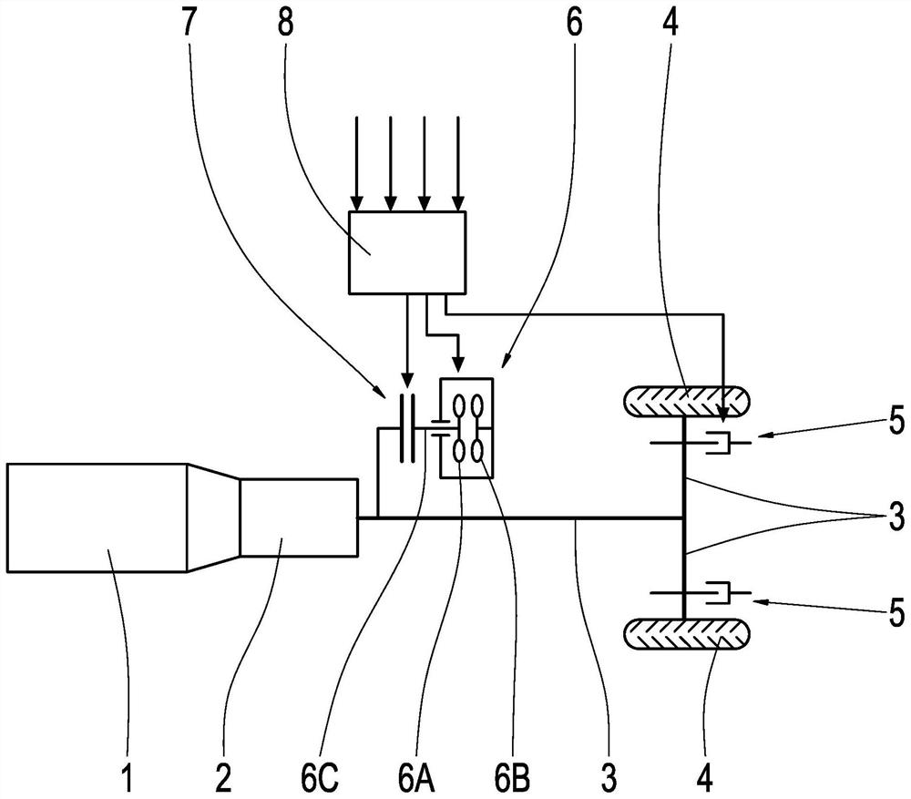
[0033] figure 1 A drive train of a vehicle, in particular a motor vehicle, in particular a truck or passenger car, is shown in plan view. The power train has a drive motor 1 for traveling the vehicle, and the power train has a transmission 2 for converting the torque of the drive motor 1 . In this case, the transmission is in particular a multi-stage shift transmission. Thus, the transmission can be, for example, an automated shift transmission or an automatic shift transmission. A transaxle 3 of the drive train is arranged on the output side of the transmission 2 . Drive axle is connected with drive wheel 4. The drive force and thus the corresponding drive torque and the corresponding drive power can thus be transmitted mechanically from the drive motor 1 to the drive wheels 4 by means of the drive train. The drive wheels 4 are supported on the roadway surface. Therefore, the vehicle can be driven by the drive motor 1 during the traction operation of the vehicle.

[003...


PUM


Abstract

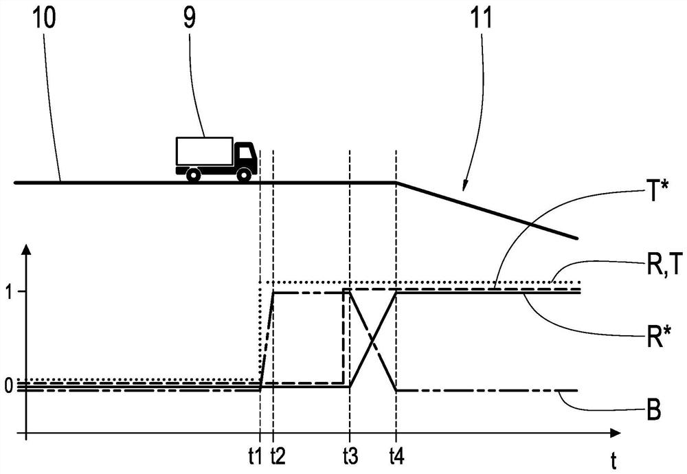
The invention relates to the possibility for operating a brake system of a vehicle (9). The brake system comprises a service brake (5) and a reduction gear (6), and comprises a disconnect clutch (7) for coupling and decoupling the reduction gear (6) from a force flow of a drive train (1, 2, 3, 4) of the vehicle (9). The service brake (5) is actuated and the disconnect clutch (7) is closed in the event of a request (R) to brake the retarder (6). Firstly, the service brake (5) is actuated in such a way that the braking effect of the service brake (5) corresponds to the expected braking effect ofthe transmission (6) according to the request (R) for passage of the transmission. After the disconnect clutch (7) is closed, the braking effect of the decelerator (6) is improved to a braking effectexpected by the pass request (R) of the decelerator (6) in a slope manner. And meanwhile, the braking effect of the service brake (5) is reduced in a slope manner.

Description

technical field [0001] The invention relates to a method for operating a braking system of a vehicle. The braking system has at least a service brake and a retarder as well as a separation clutch. The disconnect clutch is used to couple and decouple the speed reducer from the power flow of the vehicle's drive train. The invention also relates to a controller and a computer program product for correspondingly operating a braking system. Background technique [0002] Vehicle braking systems with a retarder are known and occur frequently especially in trucks. One of the advantages of a retarder compared to conventional service brakes, such as disc brakes or drum brakes, is its virtually wear-free operation. For this reason, retarders are primarily used to reduce the load on the worn service brakes during longer braking operations. [0003] A braking system is known from DE 198 43 580 A1 which has a friction brake and at least one wear-free permanent brake as well as an elec...

Claims


Application Information

Patent Timeline
Patent Type & Authority Applications(China)
IPC IPC(8): B60T10/00B60T13/66B60W10/02B60W10/196
CPCB60T10/00B60T13/66B60W10/02B60W10/196B60W2710/18B60T1/087B60T10/02F16D57/04
Inventor P·赫特F·奥伯霍弗M·沃尔特纳M·施耐德
Owner ZF FIEDRICHSHAFEN AG
Learn More