Ground surface maintaining device for optical cable landfill route

A route and optical cable technology, which is applied in the field of surface maintenance devices for optical cable buried routes, can solve problems such as large influencing factors, dust pollution environment, unfavorable optical cable maintenance, etc., and achieve the effect of reducing environmental damage, reducing accidental damage, and reducing damage

Inactive Publication Date: 2020-10-09
DONGYANG LUOSU ELECTRONICS TECH CO LTD
View PDF0 Cites 1 Cited by
  • Summary
  • Abstract
  • Description
  • Claims
  • Application Information

AI Technical Summary

Problems solved by technology

[0003] Generally, the laying of optical cables is mostly laid by landfill. Since the optical cables are buried underground, the influence factors of receiving the ground are relatively large. If there is too much landfill soil, the pressure received by the optical cables will increase, which is not conducive to the normal operation of the optical cables. Cleaning up the excess soil directly on the ground may cause dust to pollute the environment. At the same time, if there is too little landfill soil, the optical cable will not be protected normally, which is not conducive to the maintenance of the optical cable. If the soil near the depression is used for backfilling, it will be destroyed. Surrounding environment of backfill

Method used


Image

  • Ground surface maintaining device for optical cable landfill route
  • Ground surface maintaining device for optical cable landfill route
  • Ground surface maintaining device for optical cable landfill route

Examples


Embodiment Construction

[0017] All features disclosed in this specification, or steps in all methods or processes disclosed, can be combined in any way, except for mutually exclusive features and or steps.

[0018] Combine below Figure 1-4 The present invention is described in detail, and for convenience of description, the orientations mentioned below are now stipulated as follows: figure 1 The up, down, left, right, front and back directions of the projection relationship itself are the same.

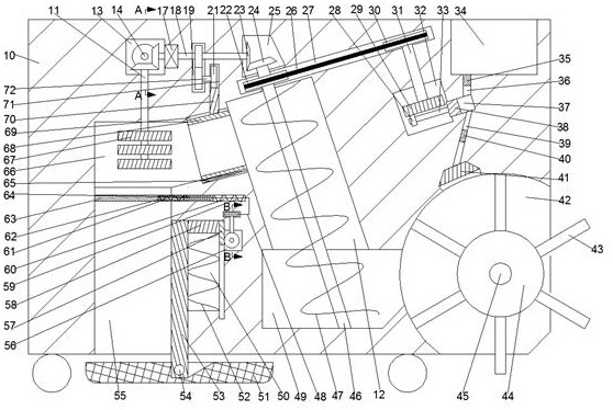
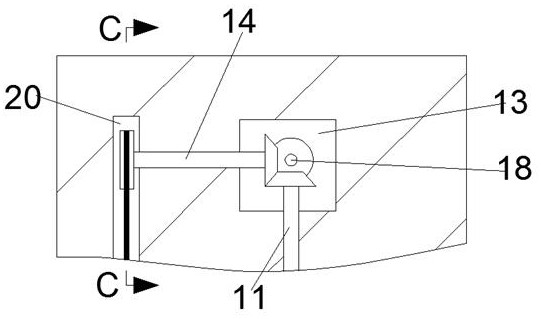
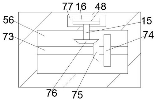
[0019] A surface maintenance device for an optical cable burial route of the device of the present invention includes a body 10, a discharge cavity 55 with an opening facing downwards is arranged in the body 10, a pit leveling device is arranged in the discharge cavity 55, and the pit leveling device It includes a pressure rod 53 slidably arranged on the right end wall of the discharge chamber 55. A pressure shaft 54 ​​located below the body 10 is fixed on the lower side of the pressure rod 53. The front a...


PUM


Abstract

The invention discloses a ground surface maintaining device for an optical cable landfill route. The ground surface maintaining device comprises a device body; and a discharging cavity with a downwardopening is formed in the device body, a pit flattening device is arranged in the discharging cavity and comprises a pressure rod slidably arranged on the right end wall of the discharging cavity, a pressure shaft located below the device body is fixed to the lower side of the pressure rod, and the front side and the rear side of the pressure shaft are rotationally connected with pressure plates.Redundant soil above the optical cable route can be excavated to ensure that the pressure borne by the optical cable route is average, protection of an optical cable is facilitated, the excavated soilcan be subjected to water-spray dust falling, damage to the environment in the transfer process is reduced, the stored soil further ensures that at land sunken positions, the sufficient soil exists for backfilling operation, and the backfilling operation can be completed without excavating soil nearby the sunken positions.

Description

technical field [0001] The invention relates to the technical field of maintenance of buried optical cables, in particular to a surface maintenance device for buried routes of optical cables. Background technique [0002] Optical cables are manufactured to meet optical, mechanical or environmental performance specifications. It is a communication cable assembly that uses one or more optical fibers placed in a sheath as a transmission medium and can be used individually or in groups. [0003] Generally, the laying of optical cables is mostly laid by landfill. Since the optical cables are buried underground, the influence factors of receiving the ground are relatively large. If there is too much landfill soil, the pressure received by the optical cables will increase, which is not conducive to the normal operation of the optical cables. Cleaning up the excess soil directly on the ground may cause dust to pollute the environment. At the same time, if there is too little landfil...

Claims


Application Information

Patent Timeline
Patent Type & Authority Applications(China)
IPC IPC(8): E02F5/22E02F3/76E02F3/78E02F3/80
CPCE02F3/76E02F3/78E02F3/80E02F5/223E02F5/226
Inventor 陈灿
Owner DONGYANG LUOSU ELECTRONICS TECH CO LTD
Why Eureka
Try Eureka