Novel head fixing device for ophthalmologic examination

An ophthalmological examination and fixation technology, which is applied in application, medical science, contraceptives, etc., can solve the problems affecting the user's experience of using the fixation device and the poor fixation effect of the patient's head, etc., and achieves rich functions, good fixation effect, and good The effect of fixed functions

Inactive Publication Date: 2020-10-13
李佳
View PDF1 Cites 1 Cited by
  • Summary
  • Abstract
  • Description
  • Claims
  • Application Information

AI Technical Summary

Problems solved by technology

[0004] However, due to the relatively simple structure of the fixing device, the patient's head can still move after being fixed, so that the fixing effect of the fixing device on the patient's head is poor, which affects the user's experience of using the fixing device

Method used


Image

  • Novel head fixing device for ophthalmologic examination
  • Novel head fixing device for ophthalmologic examination
  • Novel head fixing device for ophthalmologic examination

Examples


Embodiment 1

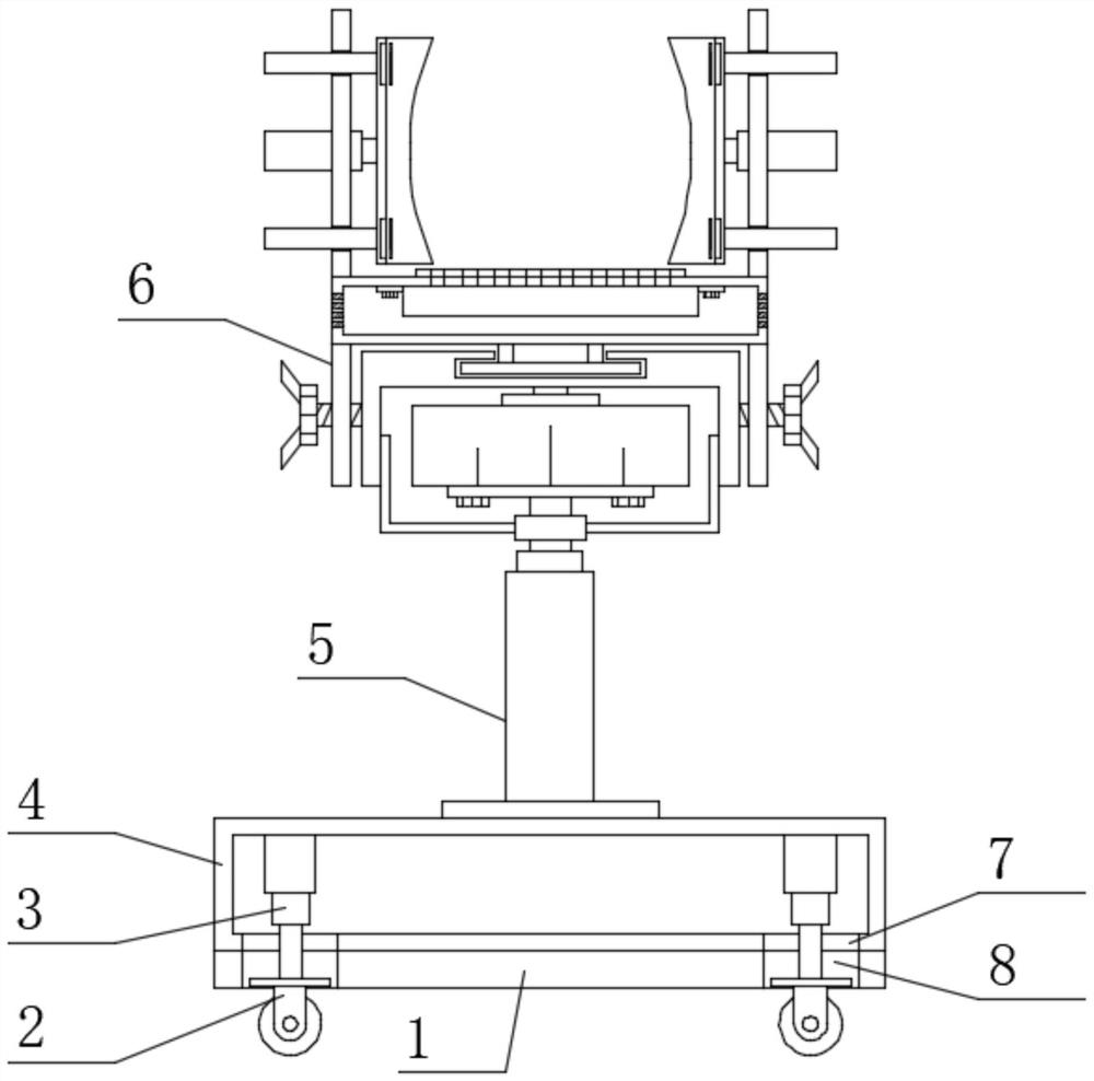
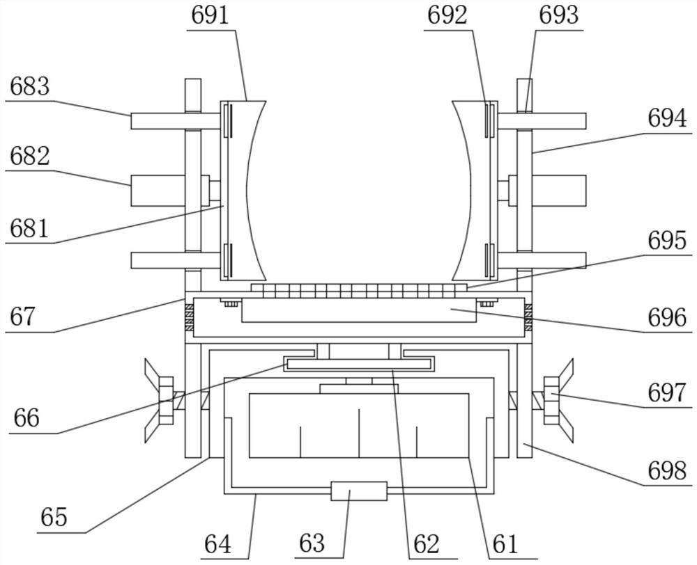
[0023] see Figure 1-Figure 3 , the present invention provides a technical solution: a novel ophthalmic examination head fixation device, comprising a support base 4, a second electric telescopic rod 5 is welded in the middle of the upper surface of the support base 4, and the top end of the second electric telescopic rod 5 is arranged Fixed mechanism 6 is arranged and fixed mechanism 6 comprises drive motor 61, and the output end of drive motor 61 is welded with the spacing base 65 of rectangular parallelepiped structure, and the top of spacing base 65 is provided with fixed base 67, and the middle part of the lower surface of fixed base 67 is welded limited position. Sliding plate 66, the limit base 65 is provided with the limit chute 62 corresponding to limit slide plate 66, and the two ends of the lower surface of fixed base 67 are also provided with the third limit plate 698 corresponding to limit base 65, The middle part of the upper surface of the fixed base 67 is provi...

Embodiment 2

[0031] On the basis of Embodiment 1, in order to make the movement of the fixing device more convenient, in this embodiment, preferably, the two ends of the support base 4 are fixed with the first electric telescopic rod 3 by bolts, and the bottom of the first electric telescopic rod 3 A ground wheel 2 is provided at the end, and a first limit through hole 7 corresponding to the ground wheel 2 is opened on the support base 4;

[0032] In order to make the use of the ground wheel 2 more reliable, in this embodiment, preferably, the top of the ground wheel 2 is fixedly connected with the first electric telescopic rod 3 by welding, and the lower surface of the support base 4 is provided with an anti-slip backing plate 1 to prevent slipping. Both ends of the backing plate 1 are provided with a second limiting through hole 8 corresponding to the ground wheel 2;

[0033] When in use, the ground wheel 2 is used to move the fixing device, making it more convenient for the user to use ...


PUM


Abstract

The invention discloses a novel head fixing device for ophthalmologic examination and belongs to the technical field of fixing devices. The novel head fixing device comprises a supporting base, wherein a second electric telescopic rod is arranged at the middle part of the upper surface of the supporting base, a fixing mechanism is arranged at the top end of the second electric telescopic rod and comprises a driving motor, a limiting base is arranged at an output end of the driving motor, a fixing base is arranged above the limiting base, a limiting slide plate is arranged at the middle part ofthe lower surface of the fixing base, a limiting sliding groove corresponding to the limiting slide plate is formed in the limiting base, third limiting plates corresponding to the limiting base arefurther arranged at the two ends of the lower surface of the fixing base, and a second cushion pad is arranged at the middle part of the upper surface of the fixing base. The novel head fixing deviceis simple in structure and convenient in use, has a good fixing function and can exert a good fixing effect on the head of a sufferer, and the user experience of the fixing device by a user is improved.

Description

technical field [0001] The invention belongs to the technical field of fixing devices, and in particular relates to a novel head fixing device for ophthalmic examination. Background technique [0002] Chinese patent (publication number CN208598365U) discloses a head fixing device for ophthalmic examination, including a bottom plate, etc.; wheels are installed at the four corners of the bottom of the bottom plate by bolts, and a lifting device is arranged in the middle of the bottom of the bottom plate. There are fixing devices on the lifting parts. [0003] The advantage of this utility model is that the height of the fixing device is adjusted by the lifting device, and the patient's head is fixed by the fixing device, thereby achieving the effect of conveniently checking the patient's eyes without affecting the inspection. [0004] However, due to the relatively simple structure of the fixing device, the patient's head can still move after being fixed, so that the fixing e...

Claims


Application Information

Patent Timeline
Patent Type & Authority Applications(China)
IPC IPC(8): A61B90/14A61B3/00A61F7/08
CPCA61B3/00A61B3/0083A61F7/08A61B90/14
Inventor 李佳
Owner 李佳
Why Eureka
Try Eureka