
Aluminum material pneumatic precise cutting machine

A cutting machine, precise technology, used in metal processing machinery parts, large fixed members, maintenance and safety accessories, etc., can solve problems such as inability to collect aluminum scraps, inability to realize automatic feeding, inability to realize aluminum cutting, etc.

Active Publication Date: 2020-10-13
益昌铝制品(太仓)有限公司
View PDF18 Cites 0 Cited by
  • Summary
  • Abstract
  • Description
  • Claims
  • Application Information

AI Technical Summary

Problems solved by technology

[0003] The currently used aluminum cutting machine can automatically feed and cut aluminum during use. The automatic feeding aluminum cutting device can only cut at a single angle, or some aluminum cutting machines can only cut at 45° Or cut at 90°, then the existing aluminum materials are no longer limited to single-angle cutting, and the position of the automatic feeding device is fixed according to the angle, which cannot achieve free-angle cutting of aluminum materials, and at the same time Automatic feeding cannot be realized when changing the angle of cutting, and the cutting blade produces a large amount of debris during the cutting process. The chip blowing device used by the current cutting machine is installed on the side of the cutting blade, and then blows the aluminum chips away from the cutting blade to prevent the impact Cutting accuracy, but the aluminum chips are scattered after being blown away from the cutting blade, and the aluminum chips cannot be collected, which is easy to affect the mechanical or electrical parts of the cutting machine

Method used


Image

  • Aluminum material pneumatic precise cutting machine
  • Aluminum material pneumatic precise cutting machine
  • Aluminum material pneumatic precise cutting machine

Examples


Embodiment Construction

[0021] The following will clearly and completely describe the technical solutions in the embodiments of the present invention with reference to the accompanying drawings in the embodiments of the present invention. Obviously, the described embodiments are only some, not all, embodiments of the present invention. Based on the embodiments of the present invention, all other embodiments obtained by persons of ordinary skill in the art without making creative efforts belong to the protection scope of the present invention.

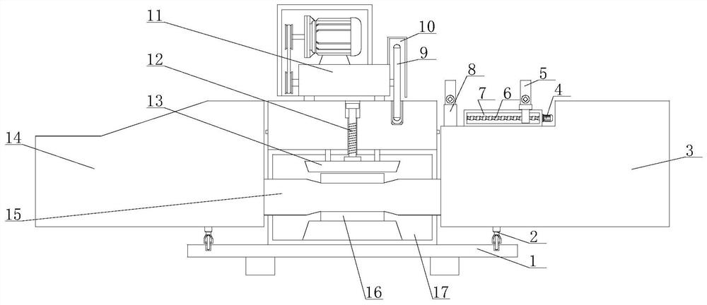
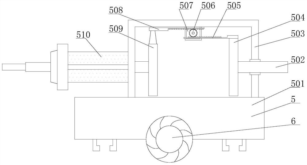
[0022] see Figure 1-5 , a pneumatic precision cutting machine for aluminum materials, comprising a base plate 1, a workbench 17 is fixedly installed on the top of the base plate 1, a power base 11 is fixedly installed on the top of the workbench 17, and a cutting blade is fixedly installed on the output end of the power base 11 9. The side of the power seat 11 is fixedly installed with an external shield 10 that matches the cutting blade 9, the bottom of the ...


PUM


Abstract

The invention relates to the technical field of cutting devices, and discloses an aluminum material pneumatic precise cutting machine. The aluminum material pneumatic precise cutting machine comprisesa base disc, a workbench is fixedly mounted at the top of the base disc, a power seat is fixedly mounted at the top of the workbench, a cutting blade is fixedly mounted at the output end of the powerseat, an external protective cover matched with the cutting blade is fixedly mounted on the side face of the power seat, a rotating table is fixedly mounted at the bottom of an inner cavity of the workbench, and an outer sleeve seat is fixedly mounted on the outer surface of the rotating table. According to the aluminum material pneumatic precise cutting machine, through cooperation of the rotating table, the outer sleeve seat, a fastening disc and an adjusting bolt, the cutting machine is divided into a cutting part and a feeding part, so that the angle between automatic feeding equipment and the cutting blade is freely adjusted in the process of cutting the aluminum material through the aluminum material cutting machine, and therefore, when the cutting angle of the device is adjusted, the automatic feeding function of the device is not influenced.

Description

technical field [0001] The invention relates to the technical field of cutting devices, in particular to a pneumatic precision cutting machine for aluminum materials. Background technique [0002] Aluminum material cutting machine is a mechanical tool specially used for cutting and processing aluminum materials. The cutting tool of aluminum material cutting machine is a circular saw blade, the saw blade is inlaid with carbide blades, and the spindle speed of the saw blade is 2000-5000 rpm. The role of the material cutting machine is to cut aluminum rods, aluminum plates, aluminum tubes, and aluminum profiles. [0003] The currently used aluminum cutting machine can automatically feed and cut aluminum during use. The automatic feeding aluminum cutting device can only cut at a single angle, or some aluminum cutting machines can only cut at 45° Or cut at 90°, then the existing aluminum materials are no longer limited to single-angle cutting, and the position of the automatic f...

Claims


Application Information

Patent Timeline
IPC IPC(8): B23Q7/00B23Q1/25B23Q11/00
CPCB23Q1/25B23Q7/00B23Q11/00B23Q11/005
Inventor 张育斌
Owner 益昌铝制品(太仓)有限公司
Learn More