Pulley block extended-range oil pumping unit
A technology of extended range and pumping unit, which is applied in the direction of exploitation fluid, wellbore/well parts, earthwork drilling and production, etc. It can solve the problems of inability to extract oil, narrow use range, small stroke, etc., and achieves easy start-up, convenient operation, The effect of improving the service life
- Summary
- Abstract
- Description
- Claims
- Application Information
AI Technical Summary
Problems solved by technology
Method used
Image
Examples
Embodiment 1
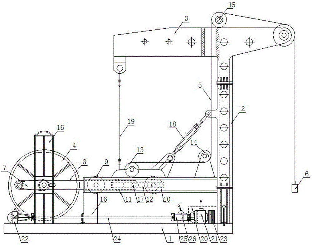
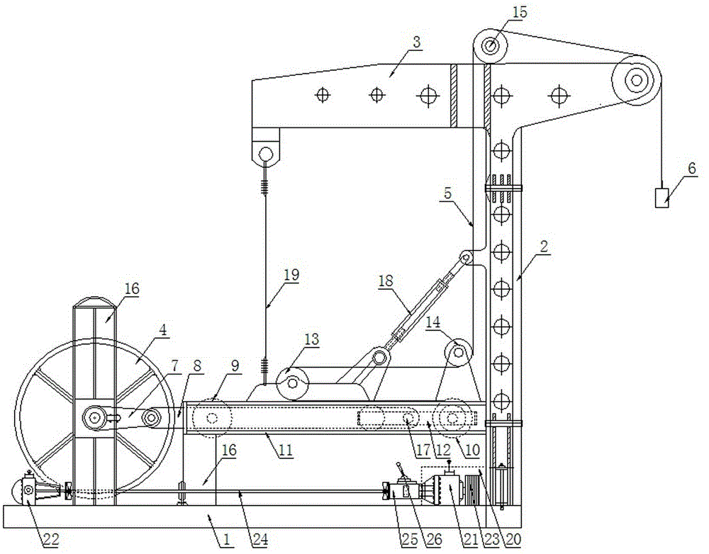
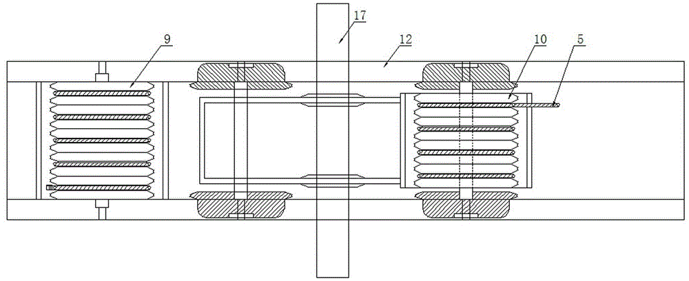
[0042] A range-extending pumping unit with a pulley block, comprising a base 1, a driving mechanism, a driving wheel 4, a sling 5, a guide wheel and a range-extending device. The range-extending device includes a first fixed pulley block 9, a second fixed pulley block 10, and a guide 11 and a walking trolley 12 arranged on a guide rail 11, the guide rail 11 is horizontally fixed above the base 1, the first fixed pulley group 9 is arranged at the end of the guide rail 11, and the second fixed pulley group 10 is fixed on the walking carriage 12 , The driving mechanism is connected with the driving wheel 4 fixed on the base 1, and the driving wheel 4 is connected with the trolley 12 and drives the trolley 12 to make linear reciprocating motion on the guide rail 11; the guide wheel is fixed on the guide rail 11 Above, one end of the suspension rope 5 is a fixed end, and the other end is wound backward through the first fixed pulley block 9 and the second fixed pulley block 10, and t...
Embodiment 2
[0052] This embodiment is basically the same as the above embodiment, the main difference is: the number of fixed pulleys in the first fixed pulley set 9 is preferably set to 5, and the number of fixed pulleys in the second fixed pulley set 10 is preferably set to 4. The fixed pulleys in the two fixed pulley sets are parallel to each other and arranged in a row. The fixed end of the sling 5 is fixed on one of the fixed pulleys at the two ends of the first fixed pulley set 9, and the remaining four fixed pulleys in the first fixed pulley set 9 The pulleys and the four fixed pulleys in the second fixed pulley set 10 cooperate with the hoist rope 5 to wind. Through the above-mentioned preferred embodiments, the stroke of the pumping unit can reach more than 6 m. However, it is not limited to the above-mentioned preferred embodiments. For example, the distance between the first fixed pulley 9 and the second fixed pulley 10, the number of fixed pulleys in the first and second fixed p...
Embodiment 3
[0055] This embodiment is basically the same as the above embodiment, the main difference is: the guide rail 11 is provided with a protective cover, the protective cover is fixed on the guide rail 11, the guide rail 11, the trolley 12, the first fixed pulley 9 and the second The two fixed pulley blocks 10 are all located in the protective cover, so as to prevent impurities such as wind and sand from entering the range extension device, thereby affecting the stable operation of the range extension device. Among them, for the smooth operation of the trolley 12, guide holes are provided on both sides of the protective cover. The length of the guide holes is the same as the length of the linear displacement of the trolley 12 on the guide rail 11, and the width of the guide holes is compatible with the diameter of the connecting shaft 17. In order to facilitate the connection of the rope 5 between the fixed pulley block and the guide wheel, the protective cover is also provided with ...
PUM
 Abstract
Description
Claims
Application Information
 - R&D
- Intellectual Property
- Life Sciences
- Materials
- Tech Scout
- Unparalleled Data Quality
- Higher Quality Content
- 60% Fewer Hallucinations
Browse by: Latest US Patents, China's latest patents, Technical Efficacy Thesaurus, Application Domain, Technology Topic, Popular Technical Reports.
© 2025 PatSnap. All rights reserved.Legal|Privacy policy|Modern Slavery Act Transparency Statement|Sitemap|About US| Contact US: help@patsnap.com


