

Upper cuff sewing machine
A sewing machine and sewing machine head technology, applied in sewing machine components, sewing equipment, cloth feeding mechanisms, etc., can solve problems such as quality problems, inconvenient sewing movement, and operational fatigue, and achieve the effect of improving automation and efficiency
- Summary
- Abstract
- Description
- Claims
- Application Information
AI Technical Summary
Problems solved by technology
Method used
Image

Examples
Embodiment Construction
[0021] Embodiments of the present invention will be described in further detail below in conjunction with the accompanying drawings.
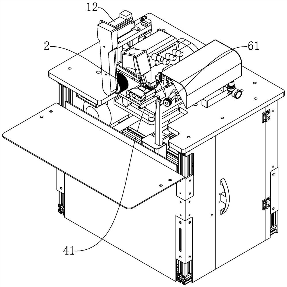
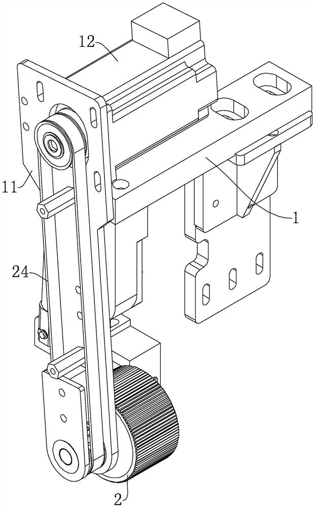
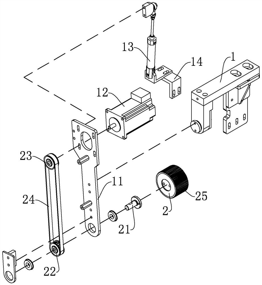
[0022] Figure 1 to Figure 6 Shown is the structural representation of the present invention.
[0023] Wherein the reference numerals are: tugboat support 1, tugboat installation arm 11, tugboat motor 12, swing cylinder 13, first cylinder installation bracket 14, tugboat 2, tugboat rotating shaft 21, first synchronous wheel 22, second synchronous wheel 23, Tugboat synchronous belt 24, axial straight tooth groove 25, expansion mounting plate 3, expansion motor 31, expansion guide rail 32, third synchronous wheel 33, fourth synchronous wheel 34, expansion synchronous belt 35, connecting block 36, expansion bracket 4, Expansion roller 41, expansion rod 42, base 5, rotating seat 51, dial mounting plate 52, dial rotating cylinder 53, pushing guide rail 54, sliding seat 55, guide bushing 56, guide shaft 57, dial motor 6 , dial 61, helical tooth gro...
PUM
 Abstract
Description
Claims
Application Information