Heat preservation exhaust pipe structure

A technology for exhaust pipes and exhaust manifolds, which is applied in the field of auto parts, can solve problems such as exhaust pipe rupture failure and limited shock absorption effect, achieve the effect of preventing rupture failure, preventing fracture failure, and meeting layout requirements

Inactive Publication Date: 2020-10-13
DONGFENG AUTOMOBILE COMPANY
View PDF11 Cites 0 Cited by
  • Summary
  • Abstract
  • Description
  • Claims
  • Application Information

AI Technical Summary

Problems solved by technology

The shock absorption effect of the conventional bellows is very limited. It can only resist the force of front and rear bending and cannot resist the irregular left and right rotation torque. Therefore, after a period of use of this structure, the problem of exhaust pipe rupture and failure will still occur.

Method used


Image

  • Heat preservation exhaust pipe structure

Examples


Embodiment 1

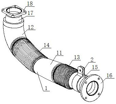
[0021] see figure 1 , a thermal insulation exhaust pipe structure The exhaust pipe 1 is an L-shaped structure, including a No. No. 1 thermal insulation pipe section 11 and No. 2 thermal insulation pipe section 12 are thermal insulation clad steel pipes. The manufacturing materials of the longitudinal high-frequency steel wire texture pipe section 13 and the transverse high-frequency steel wire texture pipe section 14 are all thermal insulation materials. The No. 1 thermal insulation pipe section 11 1. The longitudinal high-frequency steel wire pattern pipe section 13 is a straight pipe structure, and one end of the longitudinal high-frequency steel wire pattern pipe section 13 is connected with the engine exhaust manifold through the first welded steel pipe 15 and the circular French wheel disc 16 successively. The other end of the pipe section 13 is connected to one end of the horizontal high-frequency steel wire line pipe section 14 through the No. 1 thermal insulation pipe ...


PUM


Abstract

The invention discloses a heat preservation exhaust pipe structure. The heat preservation exhaust pipe structure is of an L-shaped structure and comprises a first heat preservation pipe section, a second heat preservation pipe section, a longitudinal high-frequency steel wire line pipe section and a transverse high-frequency steel wire line pipe section, wherein the first heat preservation pipe section and the longitudinal high-frequency steel wire line pipe section are each of a straight pipe structure, one end of the longitudinal high-frequency steel wire line pipe section is connected withan engine exhaust manifold, and the other end of the longitudinal high-frequency steel wire line pipe section is connected with one end of the transverse high-frequency steel wire line pipe section through the first heat preservation pipe section; and the second heat preservation pipe section and the transverse high-frequency steel wire line pipe section are each of an arc-shaped tubular structure, and the two ends of the second heat preservation pipe section are connected with the other end of the transverse high-frequency steel wire line pipe section and an air inlet of a silencer correspondingly. According to the design, the arrangement requirement of the exhaust pipe is met, and the exhaust pipe is prevented from being broken and losing efficacy due to high-frequency vibration.

Description

technical field [0001] The invention belongs to the field of auto parts, and in particular relates to a thermal insulation exhaust pipe structure. This structure can avoid deformation, bending or fracture of parts caused by high-frequency vibration. Background technique [0002] The exhaust port side of the automobile fuel engine is usually equipped with a muffler and other devices to reduce the exhaust volume, and the two are connected through the exhaust pipe. Due to the special use environment of the car, it is often necessary to drive on bumpy roads, so that the exhaust pipe will be subjected to high-frequency vibrations. Therefore, the exhaust pipe needs to maintain and withstand the relative movement of irregular left and right rotation twists and front and rear bending inside for a long time. Aiming at this problem, the conventional method is to set a corrugated pipe on the exhaust pipe, and use the corrugated pipe to absorb the relative displacement or vibration bet...

Claims


Application Information

Patent Timeline
Patent Type & Authority Applications(China)
IPC IPC(8): F01N13/08F01N13/14F01N13/16
CPCF01N13/08F01N13/14F01N13/16
Inventor 王光艳王传雄
Owner DONGFENG AUTOMOBILE COMPANY
Why Eureka
Try Eureka