
Imaging device and method, and endoscope system

An imaging device and imaging surface technology, applied in the field of optical systems, can solve problems such as limited depth of field, affecting image resolution, and inability to adjust focus, and achieve the effect of expanding the range of depth of field

Inactive Publication Date: 2020-10-13
CHONGQING JINSHAN SCI & TECH GRP
View PDF9 Cites 0 Cited by
  • Summary
  • Abstract
  • Description
  • Claims
  • Application Information

AI Technical Summary

Problems solved by technology

[0002] Due to the limited space of the endoscope application scene, the optical lens used in the endoscope system is usually a fixed-focus lens with a fixed image distance, that is, it cannot be adjusted. Therefore, the use of this type of endoscope system can only clearly observe the limited object distance. For scenarios within the scope, please refer to figure 1 As shown, the limited object distance range is called the depth of field. Imaging at the farthest or closest point of the depth of field will present the largest acceptable diffuse spot on the photoelectric imaging surface. When the object is outside the depth of field range, the diameter of the diffuse spot is larger than Pixel pitch, affecting image resolution
Therefore, the depth of field of the existing endoscope system is limited, so that there is a lot of inconvenience in the actual application of the endoscope system

Method used


Image

  • Imaging device and method, and endoscope system
  • Imaging device and method, and endoscope system
  • Imaging device and method, and endoscope system

Examples


Embodiment Construction

[0035] In order to enable those skilled in the art to better understand the technical solutions in the present invention, the technical solutions in the embodiments of the present invention will be clearly and completely described below in conjunction with the drawings in the embodiments of the present invention. Obviously, the described The embodiments are only some of the embodiments of the present invention, not all of them. Based on the embodiments of the present invention, all other embodiments obtained by persons of ordinary skill in the art without making creative efforts shall fall within the protection scope of the present invention.

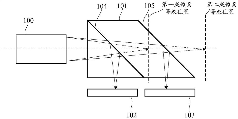
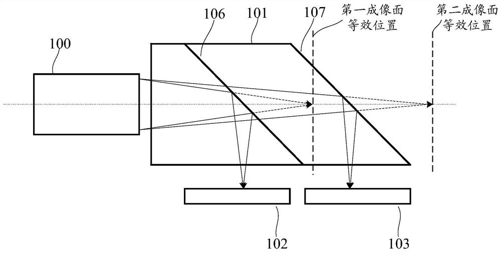
[0036] An embodiment of the present invention provides an imaging device, including a lens assembly, a beam splitting assembly, a first imaging surface, and a second imaging surface. The light output by the lens assembly splits one path of light to enter the first imaging surface, and splits another path of light to enter the second ima...


PUM


Abstract

The invention discloses an imaging device and method. A lens assembly obtains object space light and gathers the light, a light splitting assembly splits light output by the lens assembly into one path of light, the one path of light is incident to a first imaging surface, the other path of light split out by the light splitting assembly enters a second imaging surface, the first imaging surface receives the light to obtain a first image, the second imaging surface receives the light to obtain a second image, the position of the first imaging surface meets the requirement that the definition of the first image obtained when object space light within the first object distance range enters the first imaging surface meets a preset requirement, and the position of the second imaging surface meets the requirement that the definition of the second image obtained when the object space light within the second object distance range is incident to the second imaging surface meets the preset requirement. By using the imaging device, the depth-of-field range can be expanded. The invention further discloses an endoscope system.

Description

technical field [0001] The invention relates to the technical field of optical systems, in particular to an imaging device and method. The invention also relates to an endoscopic system. Background technique [0002] Due to the limited space of the endoscope application scene, the optical lens used in the endoscope system is usually a fixed-focus lens with a fixed image distance, that is, it cannot be adjusted. Therefore, the use of this type of endoscope system can only clearly observe the limited object distance. For scenarios within the scope, please refer to figure 1 As shown, the limited object distance range is called the depth of field. Imaging at the farthest or closest point of the depth of field will present the largest acceptable diffuse spot on the photoelectric imaging surface. When the object is outside the depth of field range, the diameter of the diffuse spot is larger than Pixel pitch, which affects image resolution. Therefore, the depth of field of the e...

Claims


Application Information

Patent Timeline
Patent Type & Authority Applications(China)
IPC IPC(8): G02B23/24G02B27/12
CPCG02B23/2407G02B27/126
Inventor 袁谋堃邓安鹏孙宇周健
Owner CHONGQING JINSHAN SCI & TECH GRP
Learn More