Orthopedic reduction fixing forceps capable of accurately positioning upper limb wounds

A technology of accurate positioning and fixing forceps, which is applied in the medical field, can solve the problems of difficult precise control of the clamping distance and inaccurate positioning, and achieve the effects of easy deployment of treatment, improvement of comfort, and fast clamping speed

Pending Publication Date: 2020-10-16
川北医学院附属医院
View PDF9 Cites 8 Cited by
  • Summary
  • Abstract
  • Description
  • Claims
  • Application Information

AI Technical Summary

Problems solved by technology

[0003] When the existing orthopedic fixation forceps fix the patient's upper limbs, it is dif

Method used


Image

  • Orthopedic reduction fixing forceps capable of accurately positioning upper limb wounds
  • Orthopedic reduction fixing forceps capable of accurately positioning upper limb wounds
  • Orthopedic reduction fixing forceps capable of accurately positioning upper limb wounds

Examples


Embodiment 1

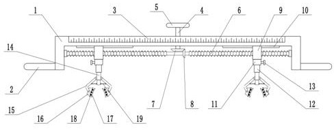
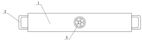
[0022] see Figure 1-3 , in an embodiment of the present invention, an orthopedic reduction fixation forceps for accurate positioning of upper limb trauma, comprising a mounting frame 1, a handle 2, a clamping arm 15, an arc-shaped plate 16 and a connecting rod 19, and the two ends of the mounting frame 1 are respectively fixedly connected There is a handle 2, which is convenient for medical staff to hold. The outer wall of the mounting frame 1 is attached with a scale 3. The rotating shaft 4 runs through the mounting frame 1. The rotating shaft 4 is rotationally connected with the mounting frame 1. The lower end of the rotating shaft 4 passes through the mounting frame 1. The top of the top extends to the bottom of the mounting frame 1, the upper end of the rotating shaft 4 is equipped with a turntable 5, and rotating the rotating disk 5 can drive the rotating shaft 4 to rotate. The inside of the mounting frame 1 is equipped with a two-way screw rod 6, and the two ends of the ...

Embodiment 2

[0024] On the basis of Embodiment 1, a buffer mechanism is installed on the inner wall of the arc-shaped plate 16, the buffer mechanism includes a buffer plate 17, a spring 18, and springs 18 are distributed on the inner wall of the arc-shaped plate 16, and the ends of the spring 18 are fixedly connected with Buffer plate 17, utilize buffer plate 17, spring 18 can play the effect of buffering, and in clamping process, buffer plate 17 and patient's upper limb join place, improve patient's comfort level.

[0025] In combination with Embodiment 1 and Embodiment 2, the working principle of the present invention is: before the treatment, turn the turntable 5 to drive the rotating shaft 4 to rotate, thereby driving the two-way screw rod 6 to rotate synchronously through the driving bevel gear 7 and the driven bevel gear 8, When the two-way screw rod 6 rotates, the slider 9 can slide along the slide rail 10, so that the two sliders 9 can move toward each other or move backwards. The o...


PUM


Abstract

The invention relates to the technical field of medical treatment, in particular to orthopedic reduction fixing forceps capable of accurately positioning upper limb wounds. The forceps comprise a mounting frame, a handle, clamping arms, an arc-shaped plate and a connecting rod, wherein a graduated scale is attached to the outer side wall of the mounting frame; a rotating shaft penetrates through the mounting frame; a bidirectional screw rod is mounted in the mounting frame; sliding blocks sleeve the bidirectional screw rod; the sliding blocks are in threaded connection with the bidirectional screw rod; sleeves are fixedly connected to the lower surfaces of the sliding blocks; mounting columns are mounted in the sleeves; telescopic mechanisms are fixedly connected to the lower ends of the mounting columns; and the clamping arms are symmetrically arranged on the left side and the right side of each telescopic mechanism. The distance between the two sliding blocks can be accurately adjusted according to an injured part of a patient by rotating a rotary disc, so that the purpose of accurate positioning is achieved; the upper limbs of the patient can be rapidly clamped through the telescopic mechanisms and the clamping arms, so that the clamping speed is high, and a doctor can conveniently perform treatment; and in the clamping process, the buffering effect can be achieved through abuffering mechanism, so that the comfort degree of the patient is improved.

Description

technical field [0001] The invention relates to the field of medical technology, in particular to an orthopedic reduction and fixation forceps for accurately locating upper limb wounds. Background technique [0002] Bone holding forceps are a kind of medical equipment used to clamp bones in orthopedic surgery and play a role of fixation and reduction. It usually consists of a pliers handle, a pliers head and gill shaft screws. The inner surface of the pliers head is mostly provided with teeth, and a locking device can be provided between the pliers handles. It is generally made of stainless steel. [0003] When the existing orthopedic fixation forceps fix the patient's upper limbs, it is difficult to accurately control the clamping distance, and the positioning is not accurate enough. Contents of the invention [0004] The object of the present invention is to provide an orthopedic reduction and fixation forceps for accurate positioning of upper limb trauma, so as to solv...

Claims


Application Information

Patent Timeline
IPC IPC(8): A61B90/14A61B17/66A61B17/28
CPCA61B90/14A61B17/66A61B17/28
Inventor 李源力
Owner 川北医学院附属医院
Why Eureka
Try Eureka