Balloon supporting rod

A support rod and balloon technology, applied in toys, entertainment, toy airplanes, etc., can solve problems such as easy to be squeezed out, easy to fly out, damage to the inflated part of the balloon, etc., achieve excellent elasticity and wear resistance, and facilitate storage and transportation , long service life effect

Active Publication Date: 2020-10-16
广东喜气洋洋印务实业有限公司
View PDF7 Cites 0 Cited by
  • Summary
  • Abstract
  • Description
  • Claims
  • Application Information

AI Technical Summary

Problems solved by technology

[0003] The patent application number is: 2015201549730. The utility model patent discloses an improved balloon support rod, which includes a rod body and a bracket installed on the rod body. The bracket includes: an insertion sleeve connected to the rod body, an upper The support ring and several support rods connected between the inserting sleeve and the upper support ring are provided with at least one set of symmetrical openings opened downward from the upper end of the upper support ring on the upper support ring, so that the tinfoil/aluminum foil balloon is practical When the balloon supports the rod, the convex edge on the balloon can just be embedded in the opening, so that the upper support ring forms a stable support for the balloon; the utility model patent has the following disadvantages: after the aluminum foil balloon is inflated, the inflated part is in an expanded state, The balloon is not easy to insert into this opening, and it is also not easy to remove when it needs to be inflated again, and the inflatable part of the balloon is easily damaged
[0004] The patent application number is: 2017205886499. The utility model patent discloses an integrated balloon support rod, including a sleeve rod. , there is a gap between the semicircular pole and the semicircular plate, the top of the semicircular plate is provided with an arc rod, the arc rod and the semicircular plate form a semicircular through hole, the On the side wall of the top of the sleeve rod, there are left and right symmetrical clamping columns for t

Method used


Image

  • Balloon supporting rod
  • Balloon supporting rod
  • Balloon supporting rod

Examples


Embodiment 1

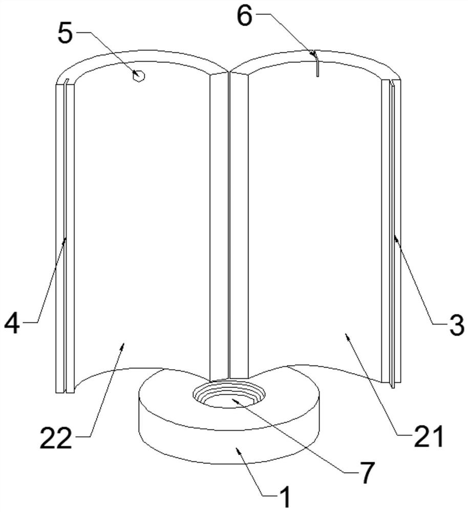
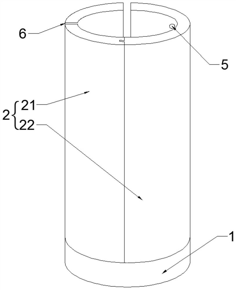
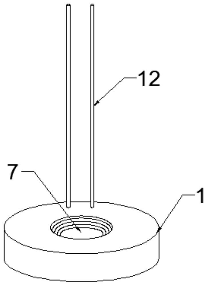
[0035] refer to Figure 1-8 , a balloon support rod, including a bracket and a rod body 8, the bracket includes a base 1 and a rotating clip 2, the rotating clip 2 includes a rotating clip 21 and a rotating clip 22, the base 1 A threaded hole 7 is provided in the center, and two connecting rods 12 are vertically fixed on one side of the threaded hole 7 on the upper surface of the base 1. Connecting hole 13 is arranged, and described rotating clip 21 and rotating clip two 22 are respectively inserted on the two connecting rods 12 through connecting hole 13, and described rotating clip one 21 and rotating clip two 22 rotate and connect connecting rod 12 There is a certain gap between one side of the two sides, and the first rotating clip 21 and the second rotating clip 22 can realize 0-270° rotation around the connecting rod 12

[0036] The middle part of a side of the rotating clip 12 away from the connecting rod 12 is radially provided with a draw-in groove 4, and the length ...


PUM


Abstract

The invention discloses a balloon supporting rod. The balloon supporting rod comprises a bracket and a rod body, the bracket comprises a base and a rotary clamping piece; the rotary clamping pieces comprise a rotary clamping piece I and a rotary clamping piece II; threaded holes are formed in the base, two connecting rods are fixedly mounted on the upper surface of the base; connecting holes are vertically formed in the bottoms of the rotary clamping piece I and the rotary clamping piece II from bottom to top; the rotary clamping piece I and the rotary clamping piece II are respectively inserted into the two connecting rods through the connecting holes; a certain gap is reserved between the sides, provided with the connecting rods, of the rotary clamping piece I and the rotary clamping piece II. The rotary clamping piece I and the rotary clamping piece I can rotate by 360 degrees around the connecting rod. A clamping groove is formed in the other side face of the rotary clamping pieceI, a protrusion clamped with the clamping groove is arranged on the other side face of the rotary clamping piece II, a round hole is formed in the upper portion of the rotary clamping piece I, a bayonet is perpendicularly formed in the upper end of the rotary clamping piece II, and a threaded connection portion is arranged on the rod body; the rod body is fixedly connected with the base through athreaded hole in a threaded mode. The upper end of the threaded connection portion is a charging end.

Description

technical field [0001] The invention relates to the technical field of balloon devices, in particular to a balloon support rod. Background technique [0002] The balloon support rod is a tool used to hold the balloon, so that the balloon can be held in the hand, so that the balloon can be grasped more easily. The types of balloons include traditional plastic balloons and aluminum film balloons. In the existing market, plastic Balloons are often fixed by balloon clips such as plum-shaped clips, and then inserted into the balloon clips through the rod body for hand-holding. For aluminum film balloons, clips are often used to pass the inflatable part of the aluminum film balloon through two splints. Clip it in place. [0003] The patent application number is: 2015201549730. The utility model patent discloses an improved balloon support rod, which includes a rod body and a bracket installed on the rod body. The bracket includes: an insertion sleeve connected to the rod body, an...

Claims


Application Information

Patent Timeline
IPC IPC(8): A63H27/10
CPCA63H27/10A63H2027/1041
Inventor 林欣
Owner 广东喜气洋洋印务实业有限公司
Why Eureka
Try Eureka