
Horizontal pushing type safety chuck

A chuck, safe technology, applied in the direction of winding strip, thin material handling, transportation and packaging, etc., can solve the problems of affecting the depth of the winding shaft, the difficulty of oblique push design, etc., to reduce processing costs and save The effect of processing time and processing concentricity guarantee

Pending Publication Date: 2020-10-16
上海韩东机械科技有限公司
View PDF0 Cites 0 Cited by
  • Summary
  • Abstract
  • Description
  • Claims
  • Application Information

AI Technical Summary

Problems solved by technology

[0006] In order to overcome the defects of the prior art, especially for the problem that the oblique push type design is difficult and affects the depth of the curling shaft, the present invention provides a flat push type safety chuck. The main body of the push plate drives the clamping block along the guide The guide groove of the shaft slides out or slides into the clamping opening, so as to place the coiling shaft or clamp the coiling shaft, the processing design is simple, and the insertion depth of the coiling shaft is not affected

Method used


Image

  • Horizontal pushing type safety chuck
  • Horizontal pushing type safety chuck
  • Horizontal pushing type safety chuck

Examples


Embodiment Construction

[0035] The present invention will be further described below in conjunction with the accompanying drawings and specific embodiments.

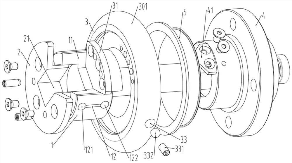
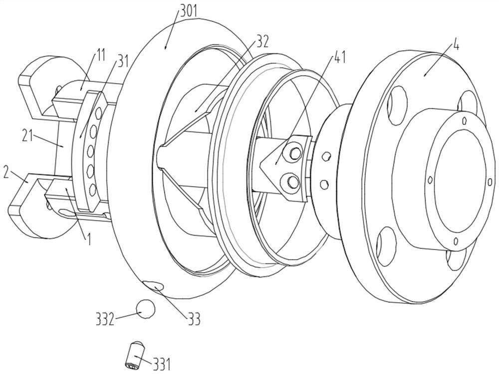
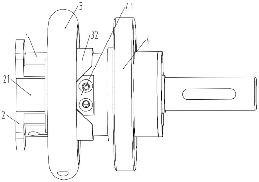
[0036] refer to Figure 1 to Figure 4 As shown, the present invention provides a flat-push safety chuck, wherein the flat-push safety chuck includes: a guide shaft 1 , a receiving assembly 2 , a push plate assembly 3 and a mounting flange 4 .

[0037] Wherein the left end of the guide shaft 1 is provided with a guide groove 11 along the axial direction. Preferably, the cross-section of the guide groove 11 is an inverted trapezoid, so as to facilitate the processing of the guide groove 11 and the clamping block 31 described below.

[0038] Wherein the receiving assembly 2 is partially embedded in the guide shaft 1, and the receiving assembly 2 is provided with a clamping opening 21 communicating with the guide groove 11 along the radial direction, so as to clamp the curling shaft. The shape of the clamping opening 21 may be square, triangular ...


PUM


Abstract

The invention relates to a horizontal pushing type safety chuck, and belongs to the technical field of clamping equipment in the curling industry. The safety chuck comprises a guide shaft, a bearing assembly, a pushing disc assembly and a mounting flange, wherein the guide shaft is provided with a guide groove; the bearing assembly is provided with a clamping opening for bearing a rolling crankshaft, a clamping block slides into the clamping opening in the axial direction of the guide shaft along the guide groove to clamp the rolling crankshaft, and slides out of the clamping opening along theguide groove to open the clamping opening to place the to-be-clamped rolling crankshaft; the mounting flange is rotationally arranged on the guide shaft in a sleeving mode, and a first deviation piece is matched with a second deviation piece on the pushing disc assembly; when the guide shaft is rotated, relative rotation of the pushing disc assembly and the mounting flange is converted into translational sliding of the pushing disc assembly in the axial direction of the guide shaft, and the clamping block is guided to automatically reset to clamp the rolling crankshaft. The design and machining of the bearing assembly and the clamping block are particularly simple, the cost and the machining time are saved, and meanwhile, the placement depth of the rolling crankshaft cannot be influencedby a horizontal pushing type clamping mode.

Description

technical field [0001] The invention relates to the technical field of clamping equipment in the curling industry, in particular to a flat-push safety chuck. Background technique [0002] In the coiling industry, the clamping of the coiling shaft is generally to use the inclined push type safety chuck. Its working principle is: turn the safety chuck to the designated position, open the safety chuck by pushing it obliquely, put the coiled shaft with coiled material into the clamping mouth of the safety chuck, and then close the safety chuck manually or through the drive shaft Drive the winding shaft to rotate together to reset; when the coil material needs to be replaced, turn the safety chuck to the designated position again, open the safety chuck to replace the new shaft. [0003] There are following defects in this inclined push type safety chuck: [0004] 1. The safety chuck and the coiling shaft have certain matching requirements. When the inclined push type design is ...

Claims


Application Information

Patent Timeline
Patent Type & Authority Applications(China)
IPC IPC(8): B65H16/02B65H19/12
CPCB65H16/02B65H19/12
Inventor 魏以龙袁钰欣张道东高洪涛
Owner 上海韩东机械科技有限公司
Learn More