

Steel rail drilling device with manual stable feeding function
A drilling device and rail technology, which is applied in the field of rail transit, can solve the problems of unguaranteed safety of operators, high physical exertion of operators, and unstable machines, so as to speed up drilling, reduce the impact of vibration, and improve The effect of stability
- Summary
- Abstract
- Description
- Claims
- Application Information
AI Technical Summary
Problems solved by technology
Method used
Image

Examples
Embodiment 1
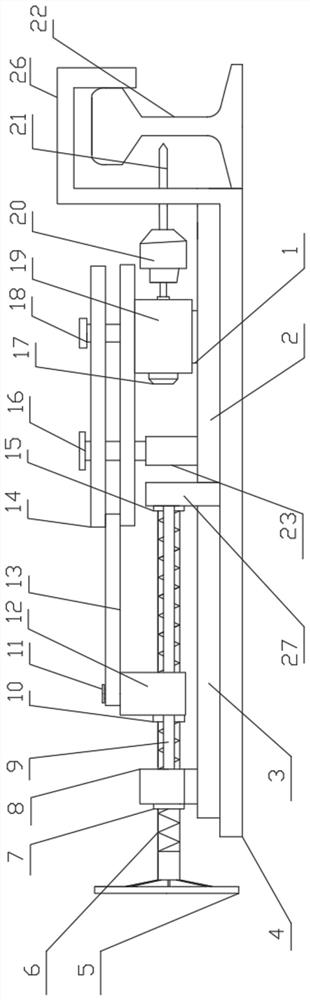
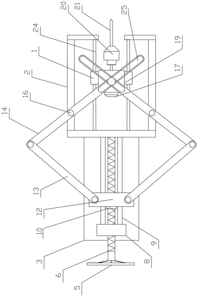
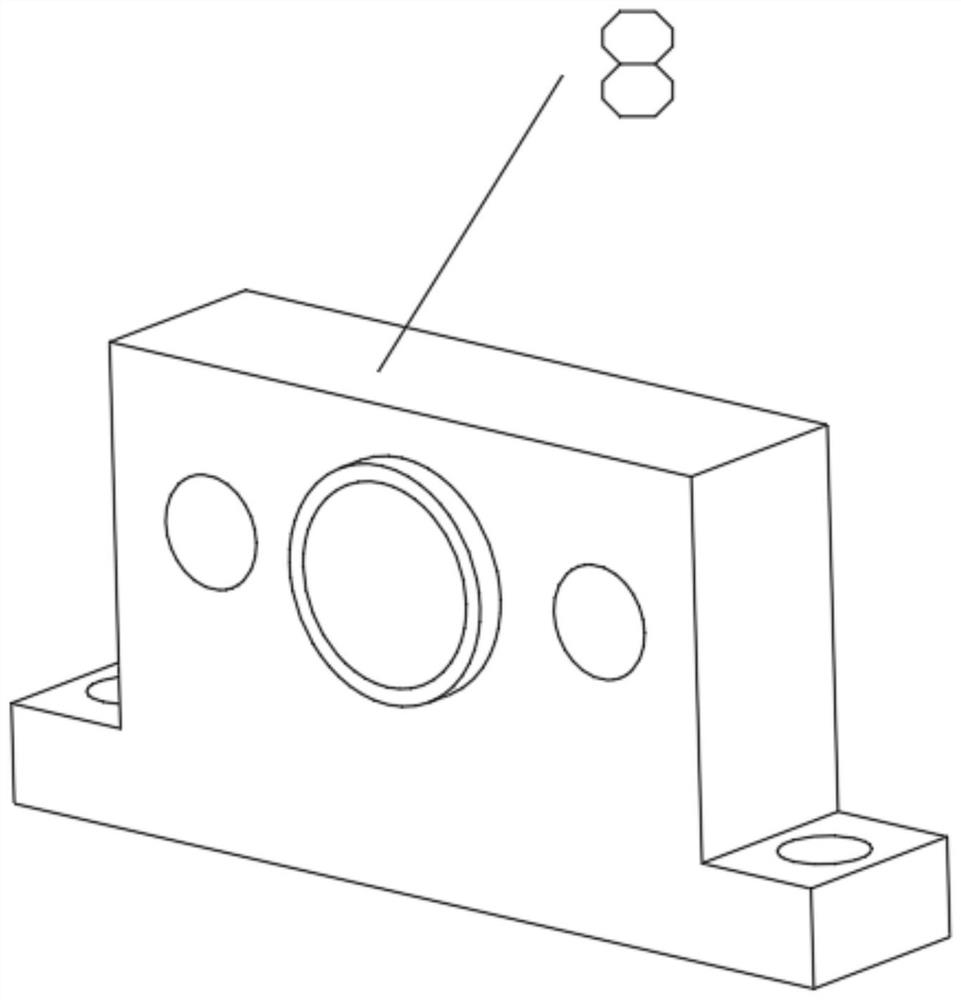
[0024] see Figure 1~4 , in an embodiment of the present invention, a rail drilling device with manual stable feeding includes a base 4, a feeding mechanism arranged on the top surface of the base 4 and a sliding mechanism arranged on the top surface of the base 4, the feeding mechanism includes Support plate 3, connecting plate 27, screw mandrel 6 and second slide block 12, supporting plate 3 is fixedly connected and arranged on the top surface of base 4, and connecting plate 27 is also fixedly connected and arranged on the top surface of base 4 and connecting plate 27 and support One end of the plate 3 is in contact, the middle of the connecting plate 27 is fixedly installed with a second rolling bearing 15, the top surface of the support plate 3 away from the side of the connecting plate 27 is fixedly installed with a bearing seat 8, and the bearing seat 8 is fixedly installed with a The first rolling bearing 7, the first rolling bearing 7 and the second rolling bearing 15 ...
Embodiment 2
[0033] see figure 1 , on the basis of Embodiment 1, the end surface of the base 4 close to the drill bit 21 is fixedly connected with a locking groove 26 .
[0034] The working principle is: before carrying out the drilling operation, the second positioning cylinder 16 is engaged and installed on the rail 22. In the present invention, the present invention is fixedly connected with the rail 22 to be drilled by setting the slot 26. The impact of vibration during drilling improves the stability of the present invention in the drilling process and further ensures the safety of workers.
[0035] The standard parts used in the present invention can be purchased from the market, and the special-shaped parts can be customized according to the instructions and the records of the accompanying drawings. The specific connection methods of each part adopt mature bolts, rivets, welding, etc. in the prior art. Conventional means, machinery, parts and equipment all adopt conventional models...
PUM
 Abstract
Description
Claims
Application Information