

Rotary boring machine for prefabricated pipe pile machining
A technology of rotary drilling machine and prefabricated pipe pile, which is applied in the direction of manufacturing tools, stone processing tools, stone processing equipment, etc., can solve the problems of easy accumulation of residues, difficult to take out, large dust, etc. The effect of fast drilling
- Summary
- Abstract
- Description
- Claims
- Application Information
AI Technical Summary
Problems solved by technology
Method used
Image

Examples
Embodiment 1
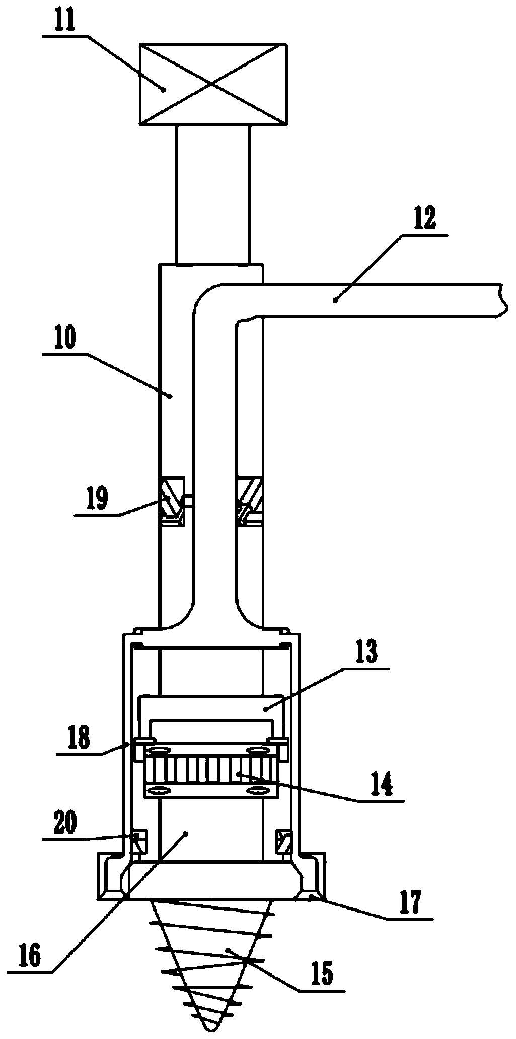
[0020] see Figure 1-2 , a rotary drilling machine for processing prefabricated pipe piles, comprising a drill rod 10, a first rotating motor 14, and a drill cutter 15; the top of the drill rod 10 is fixedly connected with a hydraulic cylinder for driving the drill rod 10 to move through a hydraulic rod 11. The drill pipe 10 is arranged as a cavity structure and a group of U-shaped mounting brackets 13 are fixedly mounted on the bottom of the drilling rod 10. A group of first rotating motors 14 are fixedly mounted on the inside of the U-shaped opening on the lower side of the mounting frame 13. The first rotation The exterior of the motor 14 is set as a stainless steel shell, which is used to improve the safety of the first rotating electric machine 14 . The lower output end of the first rotary motor 14 is rotatably connected with a group of rotating shafts 16, and the bottom of the rotating shaft 16 is fixedly equipped with a drill 15 through a mounting plate. Knife 15 can ...
Embodiment 2
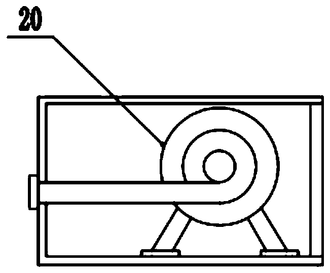
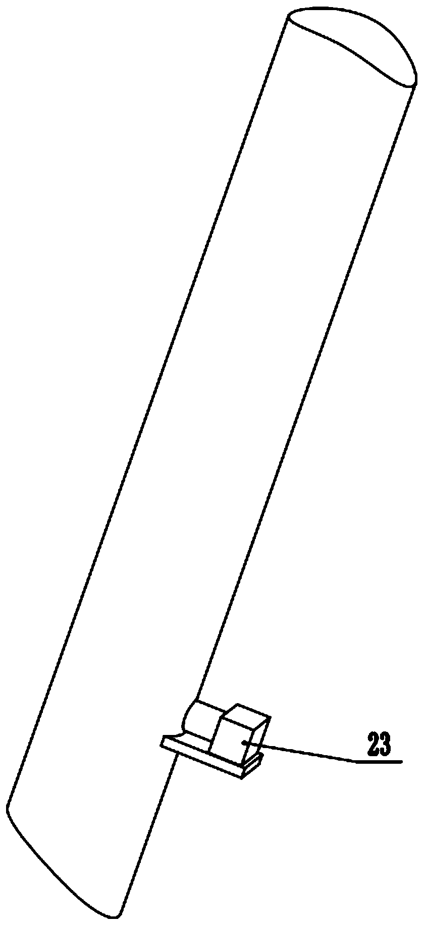
[0022] refer to Figure 3-4 , On the basis of Embodiment 1, the lower outer side wall of the waste suction pipe 18 is provided with a second rotating motor 23, and the bottom of the second rotating motor 23 is fixed on the outer side wall of the waste suction pipe 18 through a support plate, and the second rotating motor The output end of 23 faces the inside of the waste suction pipe 18 and is rotatably connected with the pull roller 25 arranged on the inside of the waste suction pipe 18 through the rotating rod. Leaked sealing ring 27. By starting the second rotating motor 23, the material picking roller 25 is directly driven to rotate inside the waste suction pipe 18, and the outer surface of the material picking roller 25 is equidistantly fixedly equipped with multiple groups of material picking plates 26 with arc-shaped structures. Rotating the direction of rotation of the motor 23 , thereby driving the shifting plate 26 to rotate upwards inside the waste suction pipe 18 ...
PUM
 Abstract
Description
Claims
Application Information