
Faucet body and manufacturing mold thereof

A faucet and body technology, applied in the field of faucet body and its manufacturing mold, can solve the problems of high manufacturing cost and complex mold structure of the faucet, and achieve the effects of low manufacturing cost, simplified structure and easy installation.

Pending Publication Date: 2020-10-16
四川文璐科技有限责任公司
View PDF0 Cites 0 Cited by
  • Summary
  • Abstract
  • Description
  • Claims
  • Application Information

AI Technical Summary

Problems solved by technology

[0007] Based on the above problems, the object of the present invention is to provide a faucet body and its manufacturing mold, which is used to solve the problems of complex structure and high manufacturing cost in the prior art for manufacturing integrally formed faucets.

Method used


Image

  • Faucet body and manufacturing mold thereof
  • Faucet body and manufacturing mold thereof
  • Faucet body and manufacturing mold thereof

Examples


Embodiment 1

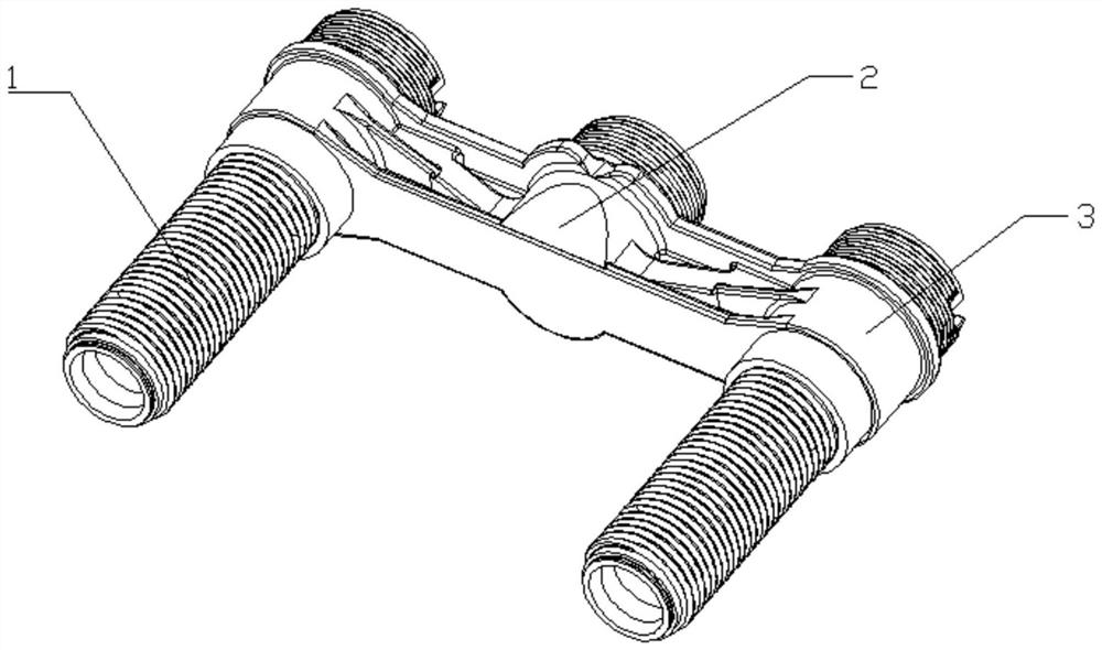
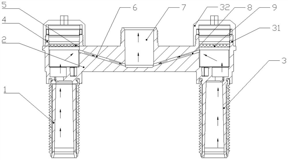
[0028] Such as Figure 1-4 As shown, a faucet body includes a beam 2, a left water inlet pipe 1 and a right water inlet pipe 3 are respectively provided on both sides of the beam 2, a water outlet 7 is opened in the beam 2, and the water outlet 7 and the left water inlet pipe 1 pass through the opening The left water passage 6 in the crossbeam 2 communicates, the water outlet 7 communicates with the right water inlet pipe 3 through the right water passage 8 opened in the crossbeam 2, the left water inlet pipe 1, the crossbeam 2 and the right water inlet pipe 3 are integrally formed, The left water passage 6 and the right water passage 8 are straight passages, the left water inlet pipe 1 is provided with a left process hole 4 on the same straight line as the left water passage 6, and the left water inlet pipe 1 is equipped with a left water passage that can be isolated. The left sealing mechanism of the water channel 6 and the left process hole 4, the right process hole 31 loca...

Embodiment 2

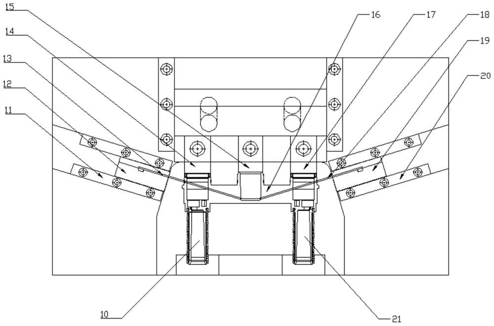
[0034] Such as Figure 1-4 As shown, on the basis of the above-mentioned embodiment 1, this embodiment provides the connection of the left water passage 6 and the right water passage 8, and the connection of the left water passage mold core 13 and the right water passage mold core 18 A preferred shape, that is, the left water passage 6 and the right water passage 8 are connected to form a V shape, and the left water passage mold core 13 and the right water passage mold core 18 are connected to form a V shape. In this case, the left sealing ring 5 and the right sealing ring 9 are all arranged horizontally, and the left process hole 4 is located on the upper side of the left sealing ring 5, the left water passage 6 is located on the lower side of the left sealing ring 5, and the right process hole 31 Located on the upper side of the right sealing ring 9, the right water passage 8 is located on the lower side of the right sealing ring 9. The left sealing ring 5 and the right sea...


PUM


Abstract

The invention relates to the technical field of faucet manufacturing, in particular to a faucet body and a manufacturing mold thereof, and aims to solve the problems of the complex structure and highmanufacturing cost of the mold for manufacturing an integrally formed faucet in the prior art. The faucet body comprises a left water inlet pipe, a cross beam, a right water inlet pipe, a left water passing channel and a right water passing channel, the left water inlet pipe, the cross beam and the right water inlet pipe are integrally formed, and the left water passing channel and the right waterpassing channel are linear channels. The mold for manufacturing the faucet body comprises a left water passing channel mold core penetrating through a left valve element hole mold core and a right water passing channel mold core penetrating through a right valve element hole mold core. According to the faucet body and the manufacturing mold, the left water passing channel and the right water passing channel of a faucet are both arranged to be linear channels, the left water passing channel mold core and the right water passing channel mold core are pulled out after corresponding molds are formed, the mold corresponding to the faucet is simpler in structure, and the production and manufacturing cost of the mold is lower.

Description

technical field [0001] The invention relates to the technical field of faucet manufacture, and more specifically relates to a faucet body and a manufacturing mold thereof. Background technique [0002] The faucet is the popular name of the water valve. It is used to control the size of the water flow. It has the effect of saving water. According to the material, it can be divided into stainless steel, cast iron, plastic, brass, zinc alloy faucet, polymer composite faucet, etc. . [0003] The manufacturing methods of faucets in the prior art mainly include the following types: one is the washboard mold, that is, the first half and the second half are injection-molded, and then the front and rear parts of the product are combined by sliding through the mold and then coated by injection molding; Buried pipe is to inject a channel tube first, and then place it in the mold and then inject and coat it again; the third is assembly, that is, the product is made into two or three se...

Claims


Application Information

Patent Timeline
IPC IPC(8): F16K11/10F16K27/00B29C45/26B29C45/73B29C45/33
CPCB29C45/26B29C45/33B29C45/7312F16K11/10F16K27/00
Inventor 范益鹏何同辉
Owner 四川文璐科技有限责任公司
Learn More