A device for manufacturing an inductor coil
A technology for making devices and inductors, which is applied to coil manufacturing and other directions, can solve the problems of cumbersome operation process and low work efficiency, and achieve the effects of simple operation, avoiding displacement and saving manpower.
- Summary
- Abstract
- Description
- Claims
- Application Information
AI Technical Summary
Problems solved by technology
Method used
Image
Examples
Embodiment 1
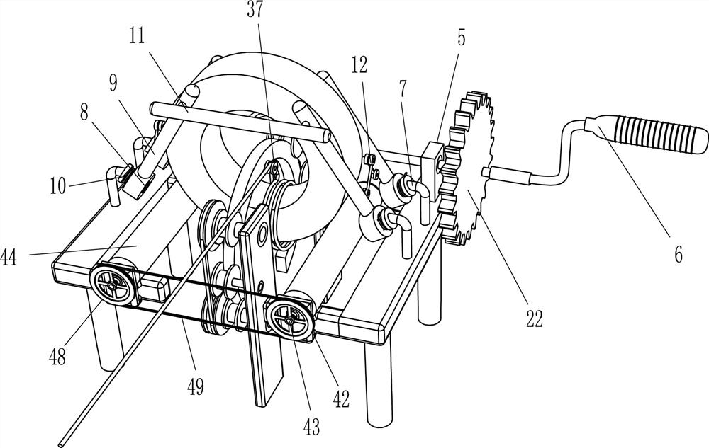
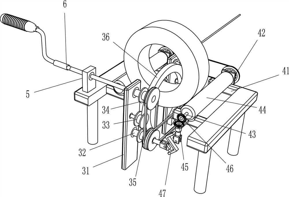
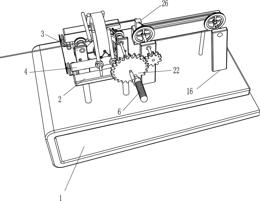
[0024] A device for making an inductance coil, such as Figure 1-3 As shown, it includes a U-shaped card seat 1, a first mounting seat 2, a second bearing seat 5 and a rocker 6. The front and rear sides of the top left side of the U-shaped card seat 1 are connected with the first mounting seat 2, and the front side The right side of the top of the first mounting seat 2 is connected with a second bearing seat 5, and the second bearing seat 5 is rotatably connected with a rocker 6, and also includes a winding device 3 and a rotating device 4, and the first mounting seat 2 on both sides A winding device 3 and a rotating device 4 are arranged between them, the winding device 3 and the rotating device 4 are connected in transmission, and the rear end of the rocker 6 is connected to the winding device 3 .
[0025] The winding device 3 includes a mounting plate 31, a first rotating shaft 32, a guide wheel 33, a first pulley 34, a first flat belt 35, a half ring threading needle 36 an...
Embodiment 2
[0029] On the basis of Example 1, such as image 3 As shown, it also includes a mounting frame 7, a second rotating shaft 8, a cylindrical clamp rod 9, an elastic member 10, a connecting rod 11 and a connecting rod 12, and the top of the first mounting base 2 is connected with a mounting frame 7, and the mounting frame 7 is two A second rotating shaft 8 is connected to the side evenly rotating type, and a cylindrical clamping rod 9 is connected to the second rotating shaft 8, and an elastic member 10 is connected between the cylindrical clamping rod 9 and the installation frame 7, and the elastic member 10 is a torsion spring. Connecting rod 11 is connected between the left side columnar clamp rod 9 left sides of both front and rear sides, and connecting rod 12 is hingedly connected on the columnar clamp rod 9, and two connecting rods 12 on the same installation frame 7 are hingedly connected.
[0030] When placing the insulating tube, you can pull the connecting rod 11 to mov...
Embodiment 3
[0032] On the basis of Example 2, such as Figure 4Shown, also include slide rail 13, slide block 14, hook 15, the 3rd bearing block 16, the 3rd rotating shaft 17, the 3rd pulley 18, the 3rd flat belt 19, elastic rope 20, pinion 21 and bull gear 22 , the top right side of the U-shaped deck 1 is connected with a slide rail 13, and the slide rail 13 is slidably connected with a slider 14, and the slider 14 is connected with a hook 15, the hook 15 can catch the wire, and the U on the front side of the slide rail 13 The top, left and right sides of the card holder 1 are connected with a third bearing seat 16, the third bearing seat 16 top is rotatably connected with a third rotating shaft 17, the third rotating shaft 17 rear side is connected with a third pulley 18, two third pulleys A third flat belt 19 is wound between 18, an elastic rope 20 is connected between the third flat belt 19 and the slider 14, a small gear 21 is connected to the front side of the third rotating shaft 1...
PUM
 Abstract
Description
Claims
Application Information
 - R&D Engineer
- R&D Manager
- IP Professional
- Industry Leading Data Capabilities
- Powerful AI technology
- Patent DNA Extraction
Browse by: Latest US Patents, China's latest patents, Technical Efficacy Thesaurus, Application Domain, Technology Topic, Popular Technical Reports.
© 2024 PatSnap. All rights reserved.Legal|Privacy policy|Modern Slavery Act Transparency Statement|Sitemap|About US| Contact US: help@patsnap.com


